IC removing device

A technology for removing liquid and positioning the platform, which is applied in the field of machinery, can solve the problems of reducing processing efficiency, increasing operating time, and burns of staff, and achieves the effects of improving processing efficiency, avoiding glass breakage, and reducing operating time

Active Publication Date: 2014-12-17
BEIJING BOE OPTOELECTRONCIS TECH CO LTD
View PDF7 Cites 5 Cited by
  • Summary
  • Abstract
  • Description
  • Claims
  • Application Information

AI Technical Summary

Problems solved by technology

[0003] The above-mentioned manual IC removal method cannot realize the fixation of the workpiece to be processed. When removing the IC, it is easy to cause the glass of the workpiece to be processed to break, and it is easy to cause burns to the staff.
Moreover, the manual IC removal method will obviously increase the operation time and reduce the processing efficiency

Method used


Image

  • IC removing device
  • IC removing device
  • IC removing device

Examples


Embodiment Construction

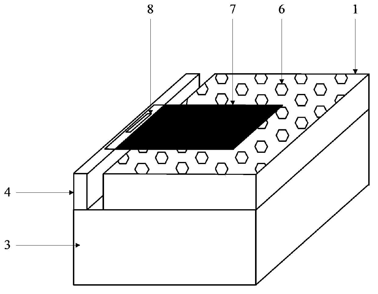
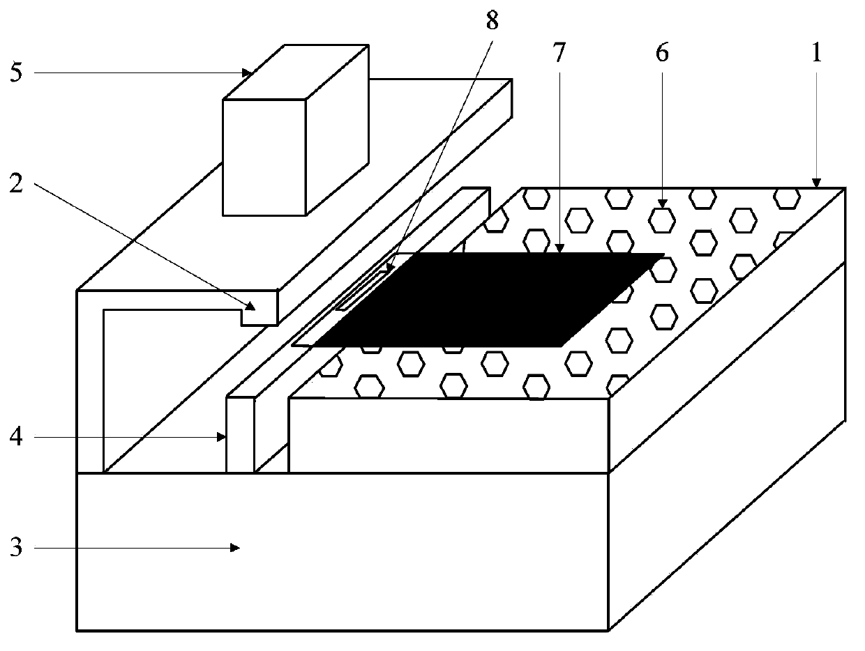
[0024] Such as figure 1 In , both the heater 4 and the positioning platform 1 are set on the operation controller 3 . Liquid crystal panels can be placed on the positioning platform 1 to wait for the processing part 7, and the processing part 7 can be protruded out of the positioning platform 1, so that the IC8 on the processing part 7 can be positioned at a position that can be heated by the heater 4 (attached or close to the heater) 4 all can be), such as: be positioned at the top of heater 4.

[0025] The operation controller 3 can control the opening and closing of the heater 4, and can also control the heating temperature of the heater 4. When the operation controller 3 controls the heater 4 to turn on, the heater 4 can heat the IC8. After a period of heating, the glue used to fix the IC8 on the workpiece 7 is softened, so the IC8 can be removed from the workpiece 7 with a tool. Remove the processing part 7 to realize the removal of IC8.

[0026] The instrument for tak...


PUM


Abstract

An integrated circuit (IC) removal device, comprising: a positioning platform for placing a piece to be treated, a heater for heating an IC on the piece to be treated, and an operation controller for controlling operation of the heater. The IC removal device significantly shortens operation time and effectively increases treatment efficiency.

Description

technical field [0001] The invention relates to the mechanical field, in particular to a device for removing an integrated circuit (IC). Background technique [0002] At present, when removing the IC on the liquid crystal panel waiting to be processed, it is usually necessary to heat the IC at a high temperature. The existing IC removal tool is a single heating table, and the staff manually heats the IC on the workpiece to be processed on the heating table, and then holds the workpiece to remove the heated IC on it. [0003] The above-mentioned manual IC removal method cannot realize the fixation of the workpiece to be processed, and when removing the IC, the glass of the workpiece to be processed is likely to be broken, and the staff is likely to be burned. Moreover, the manual IC removal method will obviously increase the operation time and reduce the processing efficiency. Contents of the invention [0004] In view of this, the main purpose of the present invention is...

Claims


Application Information

Patent Timeline
Patent Type & Authority Applications(China)
IPC IPC(8): G02F1/1333
CPCH01L21/67248H01L21/67109
Inventor 崔子巍吴志超吴昊
Owner BEIJING BOE OPTOELECTRONCIS TECH CO LTD
Why Eureka
Try Eureka