
Carbon heater with mobile quartz tube

A carbon heater and quartz tube technology, which is applied to furnace heating elements and other directions, can solve the problems of rising production costs and declining product reliability.

Inactive Publication Date: 2014-12-17
北京中科联众科技股份有限公司
View PDF6 Cites 0 Cited by
  • Summary
  • Abstract
  • Description
  • Claims
  • Application Information

AI Technical Summary

Problems solved by technology

[0006] However, in the "carbon heating element with a flange type structure" disclosed in Korean Registered Patent No. 0997957, the carbon heating element (hereinafter referred to as "carbon heater") is vertically fixed to the storage part for storing the water of the instant water heater. The supplied water is heated, so when the length of the storage part of the boiler and the instantaneous water heater is different according to the capacity of the stored water, there is a problem that although the length is somewhat different, it is necessary to install a Corresponding length of the quartz tube to the carbon heater
[0007] In addition, when a plurality of carbon heaters are required, a quartz tube corresponding to the length of each storage section must be provided, which raises the production cost accordingly.
[0008] In many cases, even if the installed carbon heater does not match the length of the storage part to some extent, it is installed regardless of this fact, so there is a problem that the reliability of the product decreases

Method used


Image

  • Carbon heater with mobile quartz tube
  • Carbon heater with mobile quartz tube
  • Carbon heater with mobile quartz tube

Examples


Embodiment Construction

[0044] Hereinafter, the present invention will be described in detail through preferred embodiments with reference to the accompanying drawings. The embodiment and the accompanying drawings are only for helping the understanding of the present invention, rather than limiting the technical scope of the present invention.

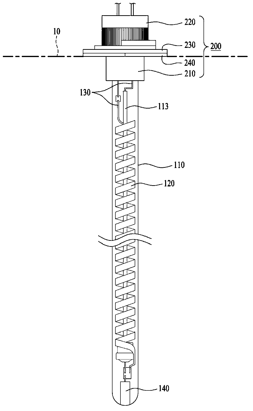
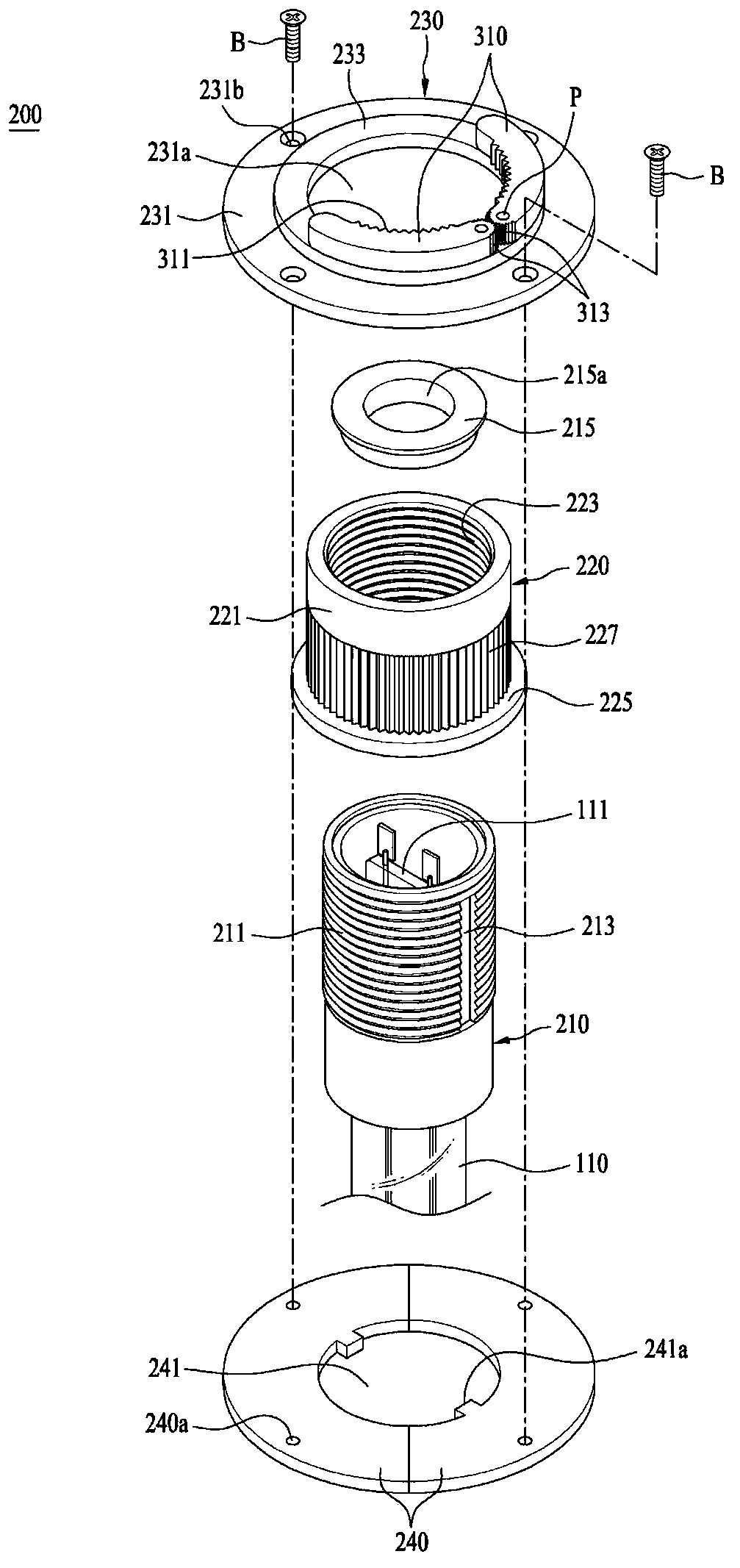
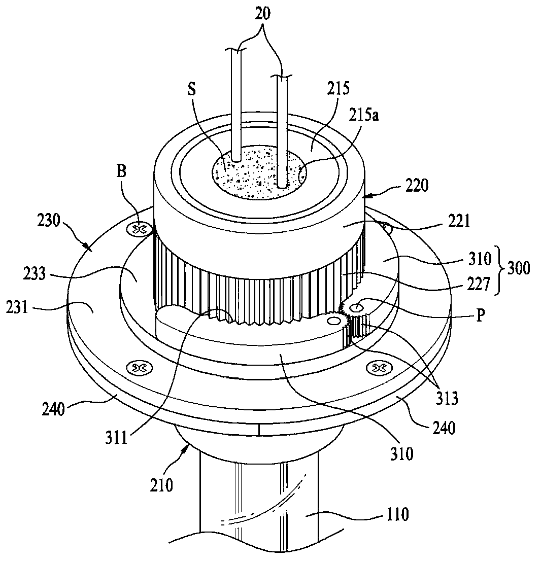
[0045] figure 1 It is a front view showing the carbon heater of the present invention, figure 2It is an exploded perspective view that disassembles the moving mechanism disposed on one side of the carbon heater in the structure of the carbon heater of the present invention, image 3 yes means figure 2 The perspective view of the main part of the bonded state, Figure 4 as image 3 The cross-sectional view of the main part of is a figure showing the state where the carbon heater of the present invention is installed on the storage part to be supplied with water, Figure 5 It is a perspective view of main parts showing a state in which the fixing mechani...


PUM


Abstract

The invention relates to a carbon heater with a mobile quartz tube. The carbon heater comprises the quartz tube, a carbon fiber heating element, power lines and a mobile mechanism, the power lines are connected with the carbon fiber heating element, and the mobile mechanism is arranged on one side of the quartz tube, so that the quartz tube can move in the lengthwise direction. The mobile mechanism comprises a bearing part, a rotating part, a flange and a gasket, a sealing part is inserted and fixed inside the bearing part, an outer thread is formed on the outer peripheral surface of the bearing part, and guide grooves are formed along the lengthwise direction of the outer thread; the rotating part is provided with a shell with the inner peripheral surface provided with an inner thread and a bending plate located at the lower end of the shell and extending and bending from the end portion to the lateral direction; the flange is combined to the position of the quartz tube to be installed with a stabilizing part provided with a communication hole in the inner side, and an accommodating groove portion is formed in a boss portion in a sectional bending manner from the upper surface of the stabilizing portion via the inner peripheral side of the communicating hole; the gasket is clamped between the flange and a setting object with a communicating hole formed in the inner side, and guiding protrusions embedded in the guide grooves of the bearing part are formed on the inner peripheral surface of the communicating hole.

Description

technical field [0001] The present invention relates to a carbon heater, and more particularly, to a carbon heater with a mobile quartz tube that supports the quartz tube when the quartz tube is set on an installation object, and makes the The quartz tube can be changed in the length direction according to the length of the installation object, so that the heat generated by the quartz tube can be utilized to the maximum. Background technique [0002] Generally, carbon is mainly composed of inorganic or organic carbon with a graphite structure, and its form can be divided into carbon filaments formed into filaments, carbon powder formed into powder, and carbon formed into cotton shapes. Felt, solidified carbon rods, etc. Such carbon is usually harder than iron and lighter than aluminum due to its elasticity and strength. In addition, according to the raw materials, it is divided into polyacrylonitrile (PAN) series, pitch (pitch) series, and rayon (Rayon) series, of which PAN...

Claims


Application Information

Patent Timeline
Patent Type & Authority Applications(China)
IPC IPC(8): H05B3/64
Inventor 陈滨王浩张雪芳
Owner 北京中科联众科技股份有限公司
Learn More