Cooling module

A technology of heat dissipation modules and heat dissipation parts, which is applied in the direction of cooling/ventilation/heating transformation, etc., can solve the heat transfer of heat dissipation parts and other problems, and achieve the effect of increasing efficiency

Inactive Publication Date: 2017-03-08
INVENTEC PUDONG TECH CORPOARTION +2
View PDF3 Cites 0 Cited by
  • Summary
  • Abstract
  • Description
  • Claims
  • Application Information

AI Technical Summary

Problems solved by technology

[0006] The technical problem to be solved by the present invention is to provide a heat dissipation module to improve the heat dissipation efficiency of the heat dissipation element and the air flow generator, and to solve the problem of heat transfer from the heat dissipation element to the housing

Method used


Image

  • Cooling module
  • Cooling module

Examples


Embodiment Construction

[0052] Below in conjunction with accompanying drawing, structural principle and working principle of the present invention are specifically described:

[0053] The detailed features and advantages of the present invention are described in detail below in the embodiments, which are sufficient to enable those skilled in the art to understand the technical content of the present invention and implement it accordingly. The related objects and advantages of the present invention can be easily understood by anyone skilled in the art. The following examples further illustrate the concept of the present invention in detail, but do not limit the scope of the present invention in any way.

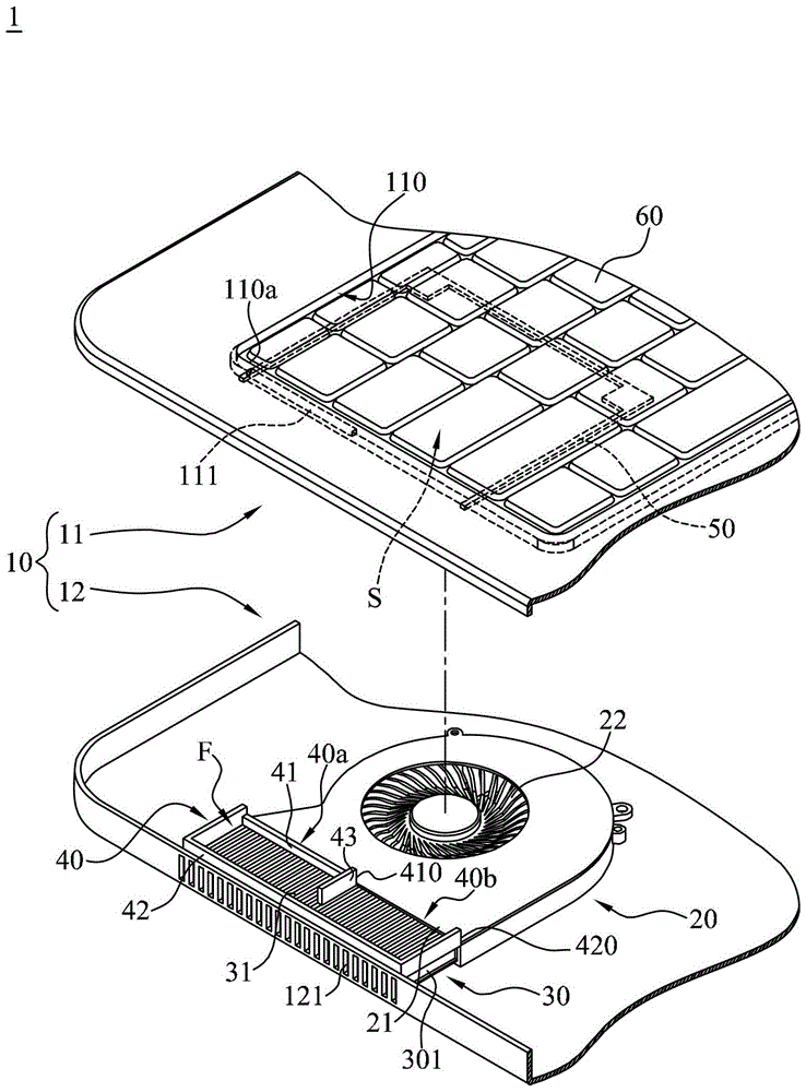
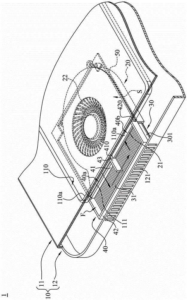
[0054] Please refer to figure 1 , is a three-dimensional exploded view of the heat dissipation module 1 according to an embodiment of the present invention. In this embodiment, the heat dissipation module 1 includes a housing 10 , an airflow generator 20 , a heat dissipation element 30 , a first ai...


PUM


Abstract

The invention describes a heat dissipation module, which comprises a housing, an airflow generator, a heat sink and a deflector. The housing has a cover portion which is provided with a through hole. The airflow generator is arranged in the housing, and has an air outlet and an air inlet. The heat sink is provided at the air outlet, and has a surface facing the cover portion. The deflector is provided in the housing to construct a passageway between the surface and the cover portion. The passageway has a first port and a second port. The first port corresponds to the through hole, while the second port corresponds to the air inlet. The heat dissipation module of the invention is capable of enabling the cover portion of the housing and the heat sink to be thermally isolated by providing cold air therebetween, enabling the cover portion not to be easily heated by the heat sink, and also ensuring the air that enters the airflow generator is the air from the outside of the housing. Therefore the heat dissipation module is able to prevent a too hot discomfort from occurring on the cover portion, and also to enhance the efficiency of the airflow generator that dissipates a heat from the heat sink.

Description

technical field [0001] The invention relates to a heat dissipation module, in particular to a heat dissipation module with a flow guide. Background technique [0002] As the computational load of electronic devices increases, the heat generated is also increasing. However, the computing speed of electronic components will decrease as their temperature rises. Excessive temperatures can even lead to damage to electronic components. Therefore, dissipating heat from electronic components so that their temperature does not rise excessively has become a problem that the industry must face. [0003] At present, the heat dissipation device in the electronic device is usually provided with a heat dissipation fin set and a fan in the casing. The heat generated by the electronic components is guided to the cooling fin group. The cooling fin group is heated by the electronic components to increase the temperature. The airflow generated by the fan is then used to blow the heat dissi...

Claims


Application Information

Patent Timeline
Patent Type & Authority Patents(China)
IPC IPC(8): H05K7/20
Inventor 许圣杰
Owner INVENTEC PUDONG TECH CORPOARTION
Why Eureka
Try Eureka