Heater for preventing carburetor from icing up

A carburetor and heater technology, applied to carburetors, machines/engines, engine components, etc., can solve the problems of increased assembly operation steps, increased number of parts, poor performance, etc., so as to suppress fuel evaporation and prevent icing , the effect of inhibiting icing

Inactive Publication Date: 2005-07-27
KEIHIN CORP
View PDF1 Cites 0 Cited by
  • Summary
  • Abstract
  • Description
  • Claims
  • Application Information

AI Technical Summary

Problems solved by technology

[0015] And, because of the needs of female screw processing, there must be a space S between the upper end of the heater mounting hole 12 and the upper bottom 13B of the electric heater 13. In order to improve the heat transfer effect of the space S, fill it with lubricant. Grease, thus the assemblability of the electric heater 13 has been greatly hindered
[0016] And, the side portion 13A with the large heating area of ​​the electric heater 13 is arranged along the fuel storage direction (up and down direction in the figure) in the float chamber main body 5, so that the fuel in the float chamber 6 is easily filled by the side wall 5A. temperature, it is not good in suppressing the evaporation of fuel in the float chamber 6
[0017] Moreover, if the electric heating wire harness (not shown) is installed on the electric heater 13, the overall height of the carburetor is actually increased, thereby hindering the load freedom of the engine.
[0018] Furthermore, the low-velocity fuel device for a carburetor as described in JP-A-9-119348 has the following problems. In this device, in order to heat the low-velocity air-fuel mixture, it is necessary to prepare the flow path 10B, the first opening 10C, and The heating member 10 consisting of the insulator 10D covering the outer periphery of the cylindrical portion 10A and the flow path member 12 consisting of the flow path 12A, the second opening 12B, and the insulator 14 covering the outer periphery result in an increase in the number of parts and a reduction in the number of assembly operations. increase, so it is not preferred

Method used


Image

  • Heater for preventing carburetor from icing up
  • Heater for preventing carburetor from icing up
  • Heater for preventing carburetor from icing up

Examples


Embodiment Construction

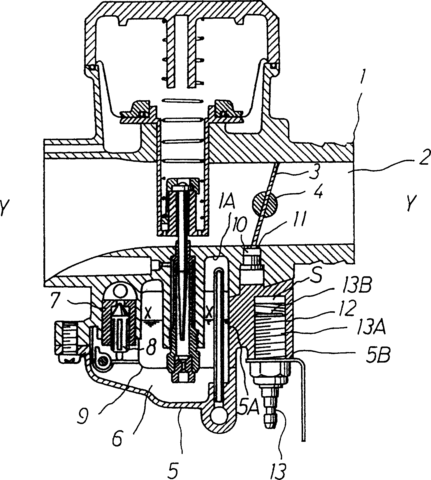
[0032] Below, according to figure 1 One of the anti-freezing heaters of the carburetor of the present invention is explained

[0033] Example.

[0034] for with figure 2 The same symbols are used for the same structural parts, and descriptions are omitted.

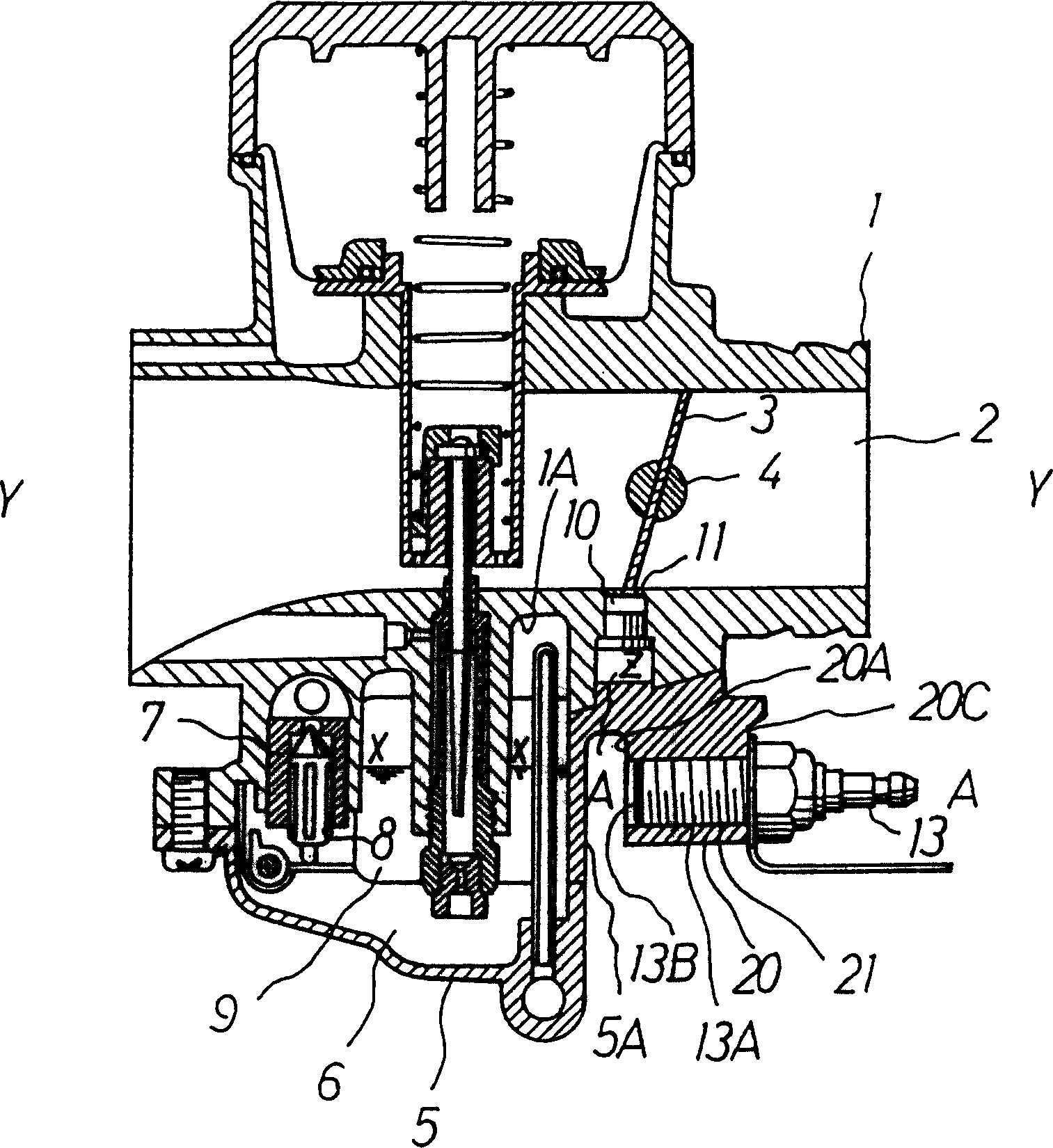
[0035] 20 is a heater mounting seat integrally formed with the float chamber main body 5, and the heater mounting seat 20 is formed parallel to the long axis Y-Y of the suction passage 2 and the fuel liquid level X-X in the float chamber.

[0036] Furthermore, a space Z is formed between the front end portion 20A of the heater mount 20 and the side wall 5A of the float chamber main body 5 .

[0037] Further, in this heater mounting base 20 , a heater mounting hole 21 is perforated from the rear end portion 20C toward the front end portion 20A, and a female thread is formed therein.

[0038] The heater mounting hole 21 is preferably formed as close to the bypass chamber 10 as possible.

[0039] Furthermore, the electr...


PUM


Abstract

The present invention provides a heater for preventing a carburetor from icing up. An air inlet passage 2 of a carburetor main body 1 is formed sideway, and the float chamber 6 on which a constant fuel liquid level X-X is formed with a float chamber main body 5 is arranged below the carburetor main body 1. An electric heater 13 is arranged on the float chamber main body 5, a longitudinal axial line A-A of the electric heater 13 is arranged roughly in parallel with the fuel liquid level X-X in the float chamber 6 as well as a longitudinal axial line Y-Y of the air inlet passage 2 and the electric heater is arranged in the neighborhood of the by-pass chamber 10. Thus, the present invention is capable of effectively warming a by-pass hole of the by-pass chamber and restraining fuel evaporation of fuel reserved in the float chamber.

Description

technical field [0001] The present invention relates to a carburetor that adjusts and controls the amount and concentration of the mixed gas supplied to the engine, and particularly relates to a heater for preventing icing ( Installation of heaters to prevent freezing). Background technique [0002] according to figure 2 An example of a conventional carburetor anti-freezing heater will be described. [0003] 1 is a carburetor main body with an air intake passage 2 installed on the side thereof, and a plate-shaped butterfly throttle valve 3 is used to control the opening and closing of the air intake passage 2 . [0004] The throttle valve 3 is screwed to the throttle valve shaft 4 rotatably supported on the carburetor body 1 , and the operator rotates the throttle valve shaft 4 to open and close the throttle valve 3 to the air intake passage 2 . [0005] The lower recess 1A of the carburetor main body 1 is closed by the cup-shaped float chamber main body 5, thereby formin...

Claims


Application Information

Patent Timeline
Patent Type & Authority Patents(China)
IPC IPC(8): F02M15/04F02MF02M3/08F02M15/02F02M15/06
Inventor 吴武夫
Owner KEIHIN CORP
Why Eureka
Try Eureka