Spike heating transmission gear

A transmission device and road stud technology, applied to lighting and heating equipment, furnace types, furnaces, etc., can solve the problems of low product quality stability, low heating efficiency, large floor space, etc., and achieve good results and convenience The effect of heating and working intensity is low

Active Publication Date: 2010-09-08
QIFENG PRECISION IND SCI TECH
View PDF1 Cites 0 Cited by
  • Summary
  • Abstract
  • Description
  • Claims
  • Application Information

AI Technical Summary

Problems solved by technology

[0004] Although this technology has the advantages of saving energy, heating quickly, and being conducive to automatic production, its heating efficiency is still relatively low, the structure is too complicated, the quality stability of the product is not high, the floor space is large, and the device is easy to overheat, and relatively high cost

Method used


Image

  • Spike heating transmission gear
  • Spike heating transmission gear
  • Spike heating transmission gear

Examples


Embodiment 1

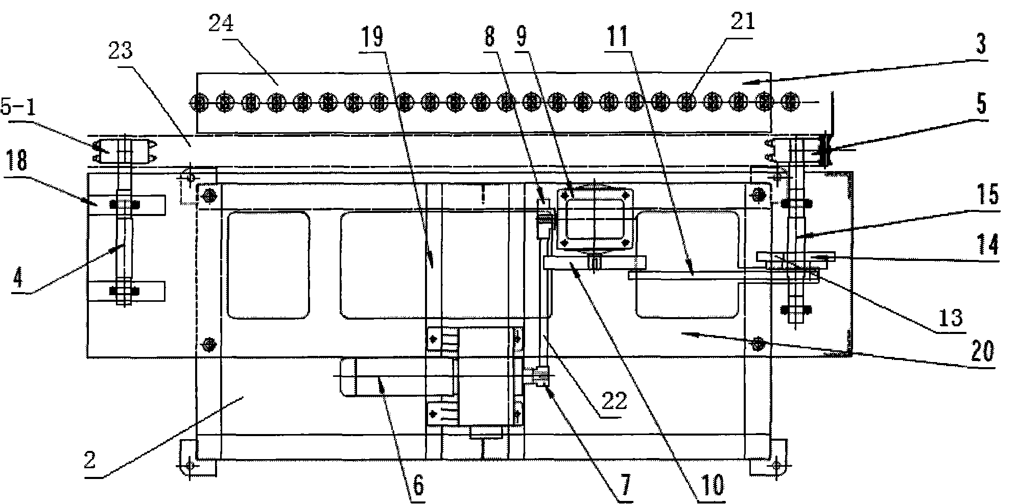
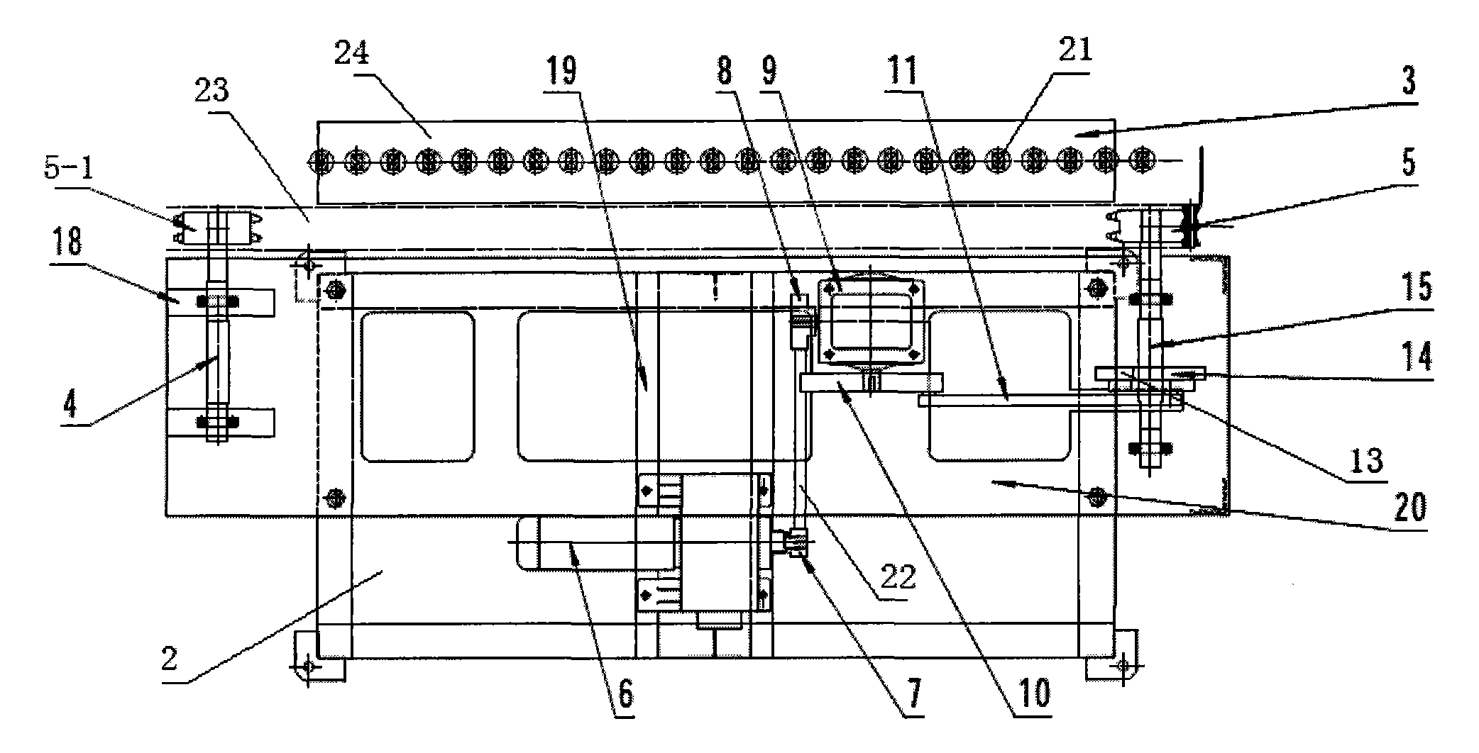
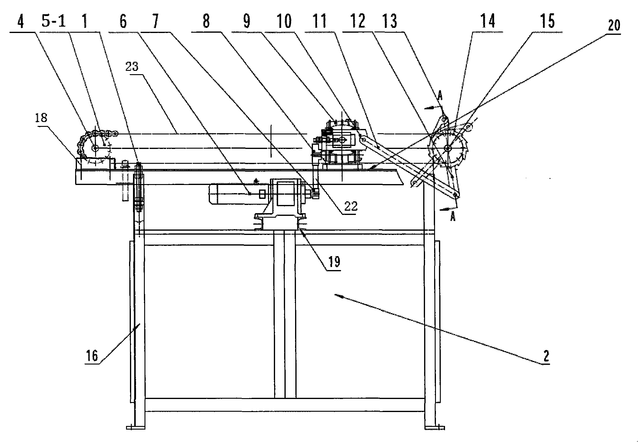
[0016] Embodiment 1: As shown in Figures 1 to 3, this embodiment consists of an electrical cabinet 2, an inductor 3, a motor 6, a reducer 9, a connecting rod 11, a rocker 12, a ratchet 14, a pawl 13, a driving shaft 15, Chain 23, driven shaft 4, driving sprocket 5, driven sprocket 5-1 and clamping plate 24 are formed, and electric cabinet 2 is the supporting component of this device. The electrical cabinet 2 is provided with a support foot 16, a channel steel 19, a bearing seat 18, a load-bearing tripod 17 and a cover plate 20. A height adjusting bolt 1 is arranged in the support foot 16 . The height adjusting bolt 1 is arranged under the cover plate 20 .

[0017] The inductor 3 is arranged on the load-bearing tripod 17 , the driven shaft 4 is installed on the bearing seat 18 , the motor 6 is bolted to the channel steel 19 , and the reducer 9 is arranged on the cover plate 20 . The large pulley 8 on the reducer 9 is connected to the small pulley 7 on the motor 6 through a be...


PUM


Abstract

The invention relates to a heating transmission device for spikes, which is applicable to the heating transmission of railway thread spikes needing to heat rolling thread. The structure of the heating transmission device for the spikes is characterized in that the device comprises a capacitor cabinet, a sensor, a motor, a reducer, a connecting rod, a rocker, a ratchet wheel, a detent, a driving shaft, a chain, a driven shaft and a clamping plate; the capacitor cabinet is arranged on the ground surface; the motor and the reducer are arranged on the capacitor cabinet; one end of the reducer is connected with the motor by a belt; the other end of the reducer is sequentially connected with the connecting rod, the rocker and the ratchet wheel; the detent is arranged on the top end of the rocker; the detent is matched with the ratchet wheel; the driving shaft and the driven shaft are respectively arranged at the two ends of the capacitor cabinet and are connected with each other by the chain; the chain is connected with the clamping plate; the sensor is arranged below the clamping plate; the head of the spike is clamped on the clamping plate; and the spike body of the spike is arranged in the sensor. The heating transmission device has the advantages of reasonable and compact structural design, good heating effect, being difficult to be over-heated and low preparation cost.

Description

technical field [0001] The invention relates to a spike heating transmission device, which is suitable for conveying and heating railway thread spikes that need to be heated and rolled. Background technique [0002] At present, the domestic railway equipment technology is relatively backward, and the ordinary joining method to produce threads has serious pollution, low energy efficiency, and unstable heating. [0003] The Chinese patent No. 200720092909.X discloses a heating device for spring bars and spikes. Its main technology is to make a flat body heater with a channel in the middle by winding four conductive pipes at the same time. Water pipe, the other large pipe body is connected with the water outlet pipe, the two large pipe bodies are fixed with screws, the screws fix a fixed plate, the two large pipe body heads are fixed with a wiring board with holes, and the two ends of the heater are fixed on the pipe. Screws are fixed, plates are fixed on the screws, the heat...

Claims


Application Information

Patent Timeline
Patent Type & Authority Patents(China)
IPC IPC(8): F27B9/24F27B9/26F27B9/36F27B9/40
Inventor 陈跃忠
Owner QIFENG PRECISION IND SCI TECH
Why Eureka
Try Eureka