Sheet application device and application method

A technology for sticking devices and sheets, which is applied in the manufacture of electrical components, circuits, semiconductors/solid-state devices, etc. It can solve the problems of increased risk of wafers and adhesive sheets, easy to fall on wafers, etc., to reduce risks and suppress settings The effect of increasing the area

Active Publication Date: 2014-12-17
LINTEC CORP
View PDF6 Cites 2 Cited by
  • Summary
  • Abstract
  • Description
  • Claims
  • Application Information

AI Technical Summary

Problems solved by technology

Therefore, in the conventional sheet sticking device, there is a disadvantage that the larger the wafer, the larger the installation area of ​​the device (horizontal projected area for device installation)
[0006] In addition, since the support device is installed horizontally, impurities such as dust in the atmosphere tend to fall on the wafer, and there is also a problem that the risk of impurities getting mixed between the wafer and the adhesive sheet increases.

Method used


Image

  • Sheet application device and application method
  • Sheet application device and application method
  • Sheet application device and application method

Examples


no. 1 approach 〕

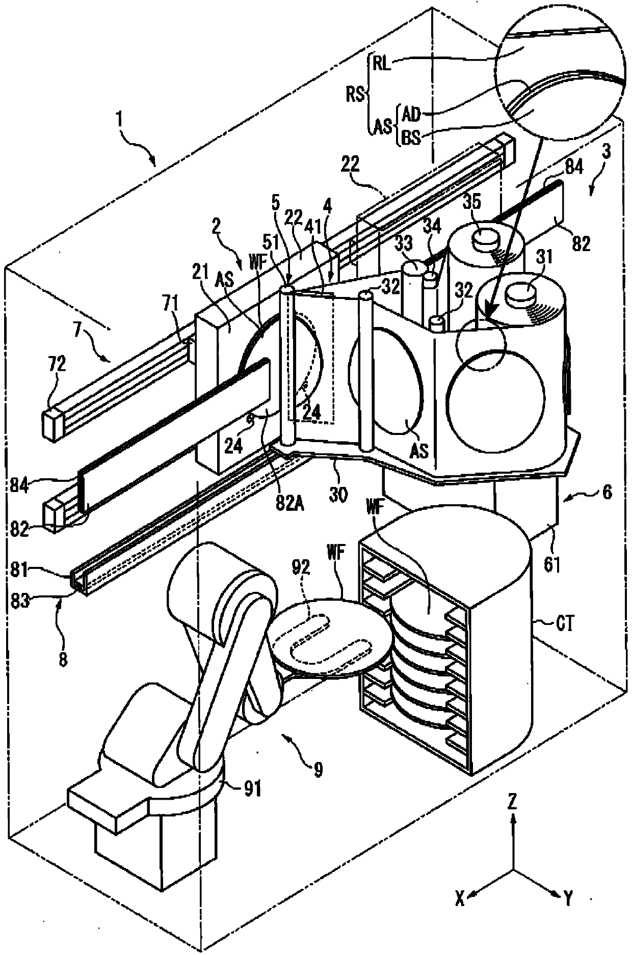
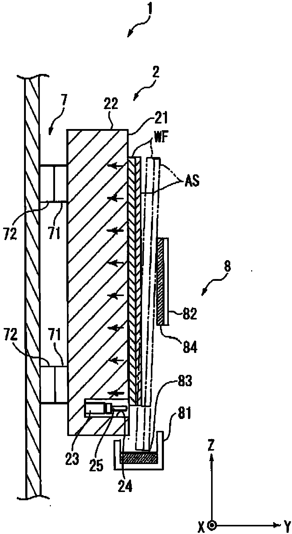
[0048] exist figure 1 Among them, the sheet sticking device 1 is a device for sticking an adhesive sheet AS on a wafer WF which is a plate-shaped member. Here, the adhesive sheet AS has an adhesive layer AD on one side of the base sheet BS, and is cut in advance into an outer shape of a predetermined size, and is temporarily attached to the tape-shaped release sheet RL via the adhesive layer AD. It is prepared in advance as the roll material RS of the object to be extracted.

[0049] The sheet sticking device 1 is provided with: a supporting device 2 for supporting the wafer WF; a drawing-out device 3 for drawing out the roll material RS; a peeling device 4 for peeling the adhesive sheet AS from the peeling sheet RL of the rolled-out material RS; A pressing device 5 for pressing the peeled adhesive sheet AS against the wafer WF; a sheet positioning device 6 as a second positioning device for positioning the adhesive sheet AS relative to the wafer WF; and making the support de...

no. 2 approach 〕

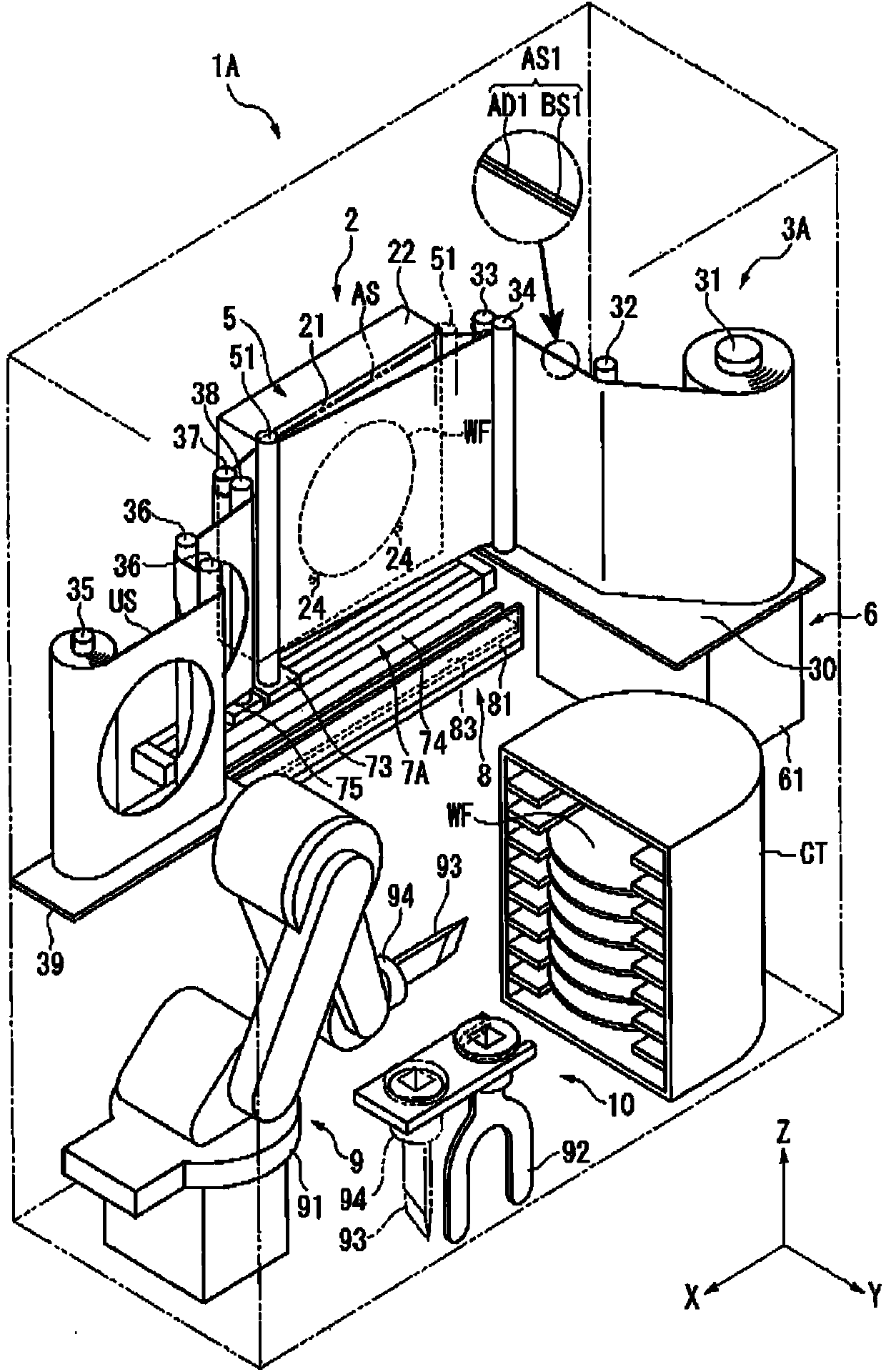
[0069] Next, based on image 3 A second embodiment of the present invention will be described.

[0070] The sheet sticking apparatus 1A of this embodiment differs from the first embodiment in that it does not include a peeling device and that it includes a cutting device 10 and has an adhesive layer AD1 on one side of the strip-shaped base sheet BS1. After sticking the tape-shaped adhesive sheet AS1 as the object to be extracted on the wafer WF, the adhesive sheet AS1 is cut. In addition, the configurations of the drawing device 3A and the moving device 7A are different from those of the first embodiment.

[0071] The take-out device 3A is equipped with: a support roller 31 that winds and supports the adhesive sheet AS1 in the form of a belt; a guide roller 32 that guides the adhesive sheet AS1; a driving roller 33 driven by a driving device not shown in the figure; The pinch roller 34 with the sheet AS1 sandwiched between it and the driving roller 33; a plurality of guide r...


PUM


Abstract

The invention provides a sheet application device and an application method. This sheet application device (1) is equipped with: a supporting means (2) that has a tilted surface (21) which is tilted with respect to a horizontal plane and is for supporting a plate-like member (WF) by means of the tilted surface (21); a feeding means (3) for feeding a rolled sheet (RS), which is obtained by temporarily adhering an adhesive sheet (AS) to one surface of a belt-like backing sheet (RL), as an object to be fed; a detaching means (4) for detaching the adhesive sheet (AS) from the backing sheet (RL) of the rolled sheet (RS) which is fed by the feeding means (3); a pressing means (5) for pressing the adhesive sheet (AS), which is detached by the detaching means (4), against the plate-like member (WF); and a moving means (7) for moving the supporting means (2) and the pressing means (5) relative to each other in the in-plane direction of the tilted surface (21) in order to apply the adhesive sheet (AS) to the plate-like member (WF).

Description

technical field [0001] The present invention relates to a sheet sticking device and a sticking method for sticking an adhesive sheet to a plate-shaped member. Background technique [0002] Conventionally, it is known that in a semiconductor manufacturing process, adhesive sheets such as protective sheets, mounting sheets, dicing tapes, and die-bonding tapes are attached to semiconductor wafers (hereinafter, sometimes simply referred to as "wafers") that are plate-shaped members. A sheet sticking device on the surface of (for example, refer to Patent Document 1). [0003] The sheet sticking device described in Patent Document 1 includes: a table for sucking and holding a wafer, a sheet sticking unit for sticking a tape-shaped adhesive sheet to the held wafer, and a cutting unit for cutting the adhesive sheet. The tape-shaped adhesive sheet is cut in a state where the tape-shaped adhesive sheet is attached, and the adhesive sheet of a predetermined shape can be attached to th...

Claims


Application Information

Patent Timeline
Patent Type & Authority Applications(China)
IPC IPC(8): H01L21/683
CPCH01L21/67132
Inventor 杉下芳昭
Owner LINTEC CORP
Why Eureka
Try Eureka