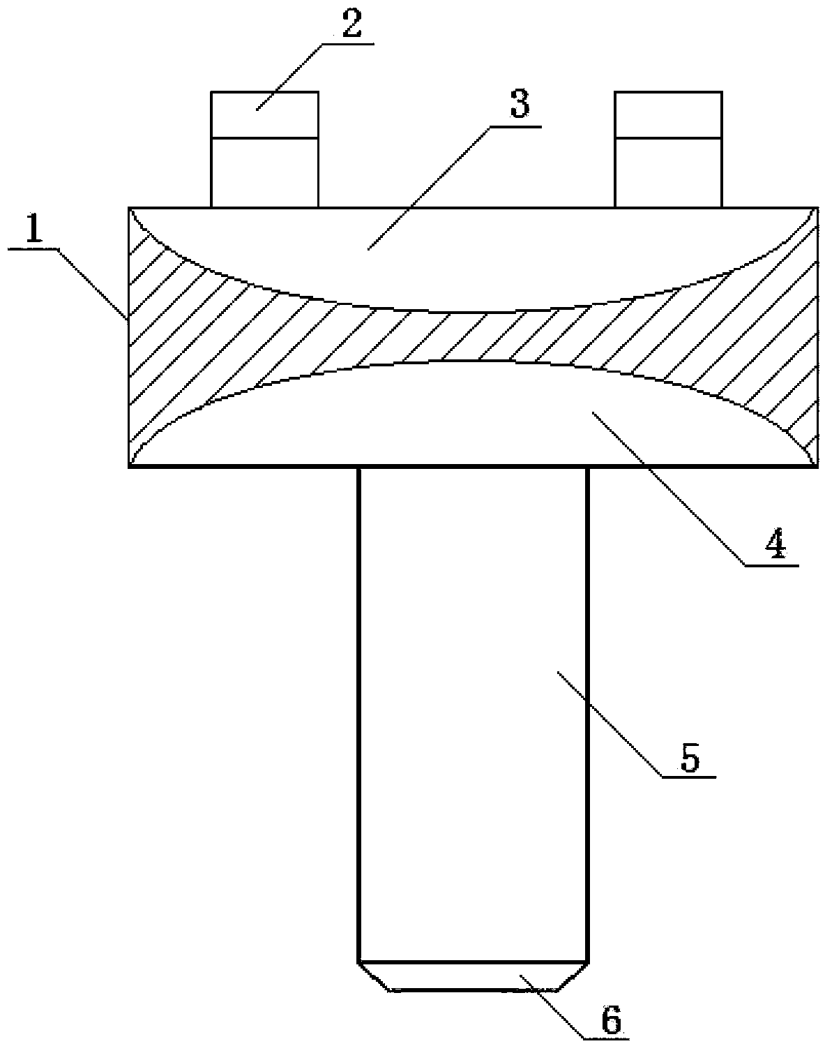
High-power punching male die structure
A punching punch, high-power technology, applied in the field of stamping abrasives, can solve the problems of low degree of automation, poor general performance, slow punching, etc., and achieve the effect of high degree of automation, low production cost and high power
Inactive Publication Date: 2014-12-24
尹克华
View PDF0 Cites 0 Cited by
- Summary
- Abstract
- Description
- Claims
- Application Information
AI Technical Summary
Problems solved by technology
[0005] Beneficial effects of the present invention: In the present invention, since the above method is adopted, the blade becomes sharper, and it is not necessary to use a larger press when punching larger holes or thicker sheets, so the present invention has the advantages of Small investment in stamping production, low production cost, high power, fast punching, simple structure, high degree of automation, good general performance, effectively overcome the existing punching dies with low power and slow punching , complex structure, low degree of automation, and poor general performance
Method used
View moreImage
Smart ImageViewing Examples
Examples
Embodiment Construction
[0009] The structure of the punching punch has a punch body (1), on which the movable sliding mold (2), punch body (5) and punch head (6) are respectively installed; among them, the punch body (1) is provided with an upper ball socket (3) and a lower ball socket (4).
Login to View More PUM
 Abstract
The invention discloses a high-power punching male die structure. The high-power punching male die structure is characterized in that movable slide dies, a male die body and a male die head are respectively mounted on a male die, and an upper ball socket and a lower ball socket are arranged on the male die. The high-power punching male die structure has the advantages of low punching production investment and production cost, high power, punching speed and automation degree, simple structure and good universality. Besides, shortcomings of low power, automation degree and punching speed, complicated structure and poor universality of existing punching dies can be effectively overcome by the aid of the high-power punching male die structure.
Description
technical field [0001] The invention relates to a punching punch structure, in particular to a high-power punching punch structure, which belongs to the technical field of punching abrasive tools. Background technique [0002] At present, in the structure of the punching die, the punching die is generally composed of a die handle and a punch. The working surface of the punch, that is, the shearing surface, is a planar structure. Although this structure has It has the advantages of simple structure, good manufacturability, and high strength. However, due to structural reasons, the blade is not sharp enough. In order to punch larger holes or thicker sheets, a larger press must be used. Therefore, the current punching dies have the defects of low power, slow punching, complex structure, low degree of automation, and poor general performance. Contents of the invention [0003] The purpose of the present invention is to provide a high-power punching punch structure with high p...
Claims
Login to View More Application Information
Patent Timeline
 Patent Type & Authority Applications(China)
IPC IPC(8): B21D28/34
Inventor 尹克华
Owner 尹克华
Features
- R&D
- Intellectual Property
- Life Sciences
- Materials
- Tech Scout
- Unparalleled Data Quality
- Higher Quality Content
- 60% Fewer Hallucinations
Learn More Browse by: Latest US Patents, China's latest patents, Technical Efficacy Thesaurus, Application Domain, Technology Topic, Popular Technical Reports.
© 2025 PatSnap. All rights reserved.Legal|Privacy policy|Modern Slavery Act Transparency Statement|Sitemap|About US| Contact US: help@patsnap.com

