Adjustable dual-purpose bearing tray

An adjustable technology for carrying trays, applied in rigid containers, containers, packaging, etc., can solve the problems of cable trays that cannot be placed horizontally, low space utilization, and cumbersome management, so as to reduce storage time, improve production efficiency, and save The effect of warehouse space

Inactive Publication Date: 2014-12-24
SHANGHAI MUNICIPAL ELECTRIC POWER CO +2
View PDF6 Cites 19 Cited by
  • Summary
  • Abstract
  • Description
  • Claims
  • Application Information

AI Technical Summary

Problems solved by technology

When the cable reel is stored in the warehouse, it cannot be placed horizontally to avoid the loosening of the cable. When it is placed vertically, it is necessary to set a stopper to prevent it from rolling. Troubled management and low space utilization

Method used


Image

  • Adjustable dual-purpose bearing tray
  • Adjustable dual-purpose bearing tray
  • Adjustable dual-purpose bearing tray

Examples


Embodiment 1

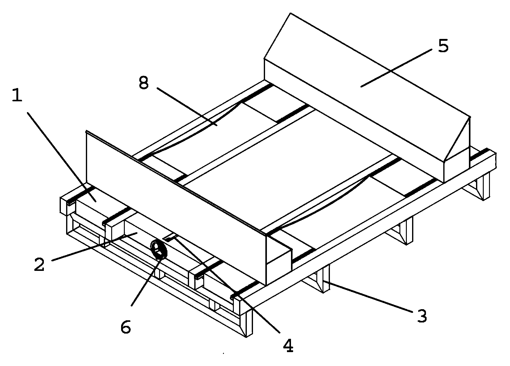
[0032] An adjustable dual-purpose carrying tray, the tray body is composed of two parallel carrying plates and a connecting plate arranged between the two carrying plates, the width of the carrying plate is 450mm, the distance is 500mm, and there are 4 supports under the carrying plate shelf.

[0033] The two connecting plates are provided with a movable screw rod along the central line, and the left and right threads of the movable screw rod are opposite.

[0034] There are two movable stop strips on the upper side of the two ends of the bearing plate. The upper cross section of the two movable stop strips is a right-angled trapezoid, and the lower part is formed with a screw hole screwed with the movable screw, which can move along the movable screw with the rotation of the movable screw. .

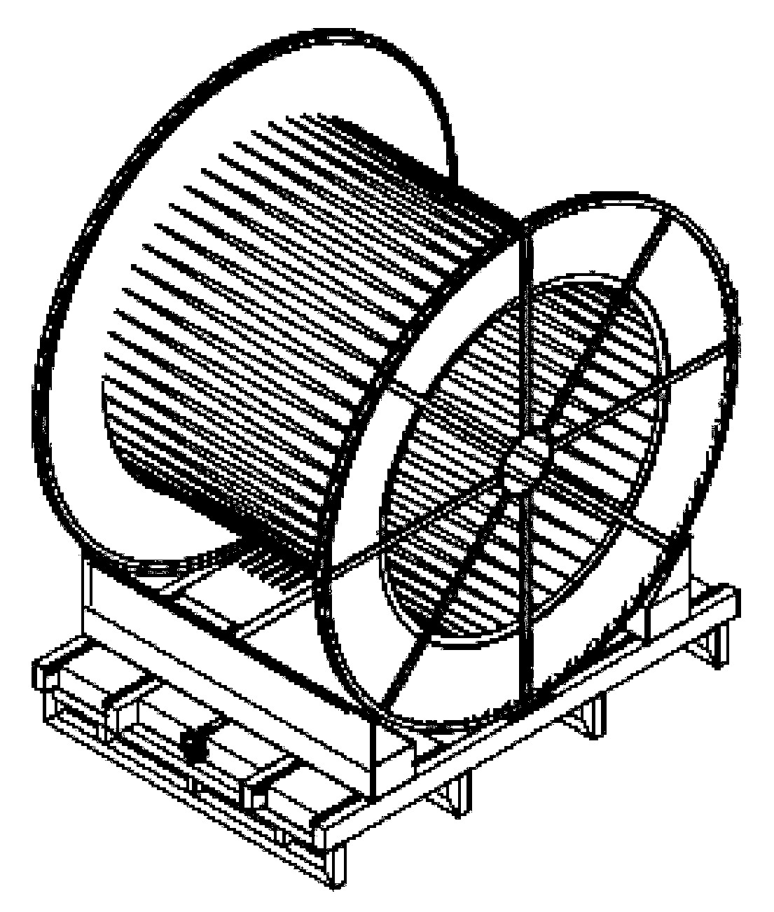
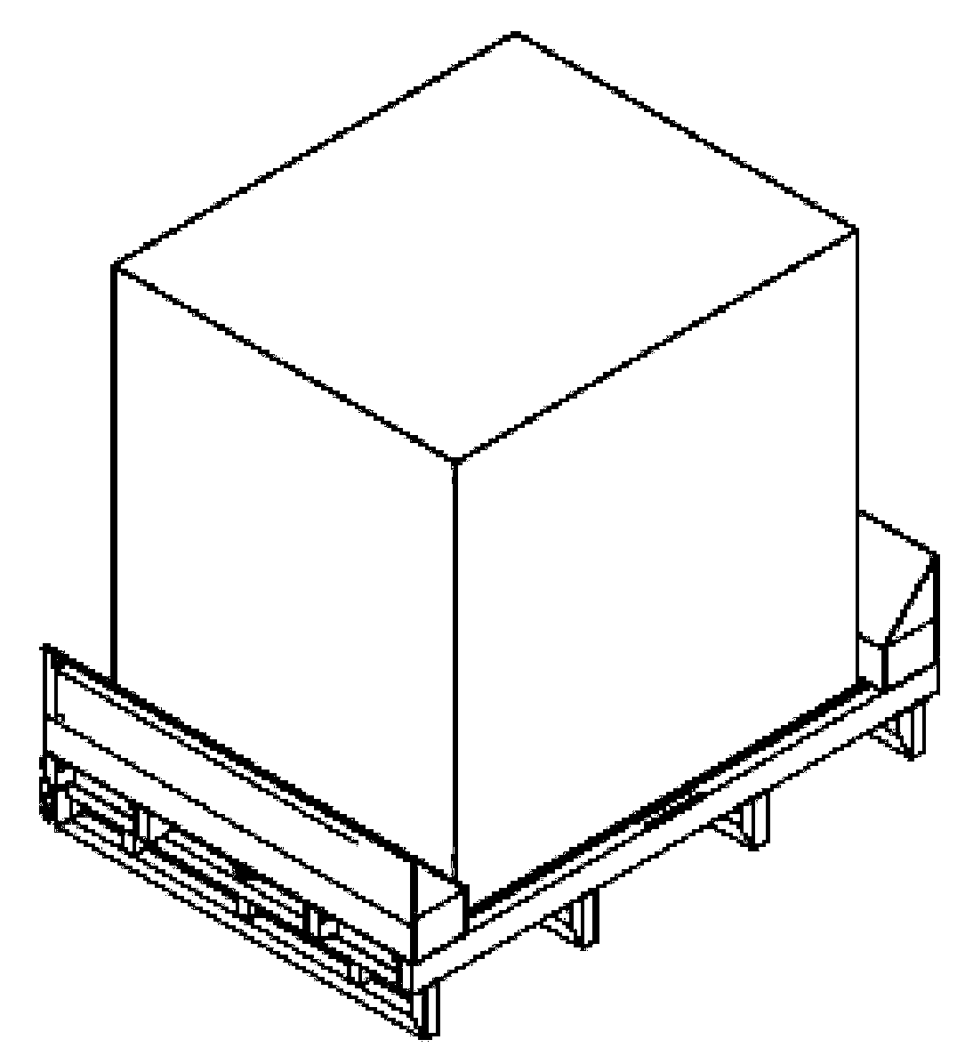
[0035] According to the adjustable dual-purpose carrying tray of the present invention, cable reels of various sizes can be placed, and goods of other shapes can also be placed. When ...

Embodiment 2

[0037] An adjustable dual-purpose carrying tray, the tray body is composed of two parallel carrying plates and a connecting plate arranged between the two carrying plates, the width of the carrying plate is 600mm, the distance is 550mm, and there are 5 supports under the carrying plate shelf.

[0038] The two ends of the two connecting plates are respectively provided with movable screws along the center line, and the upper side of the two ends of the bearing plate is provided with two movable stop strips. The holes can move respectively along the movable screw with the rotation of the movable screw.

[0039] According to the adjustable dual-purpose carrying tray of the present invention, cable reels of various sizes can be placed, and goods of other shapes can also be placed. When it is used to place the cable reel, the slope above the movable stop bar cooperates with the arc of the cable reel to act as a stopper, and the arc-shaped groove on the bearing plate accommodates a...


PUM


Abstract

The invention discloses an adjustable dual-purpose bearing tray, which comprises two strip-shaped bearing plates (1), a connecting plate (2) and framework-shaped support frames (3), wherein the two strip-shaped bearing plates (1) are transversely arranged in parallel and are used for bearing cargoes; the connecting plate (2) is arranged between the two bearing plates (1); the framework-shaped support frames (3) which are arranged below the bearing plates (1) , vertically arranged in parallel and in contact with the ground. The adjustable dual-purpose bearing tray is characterized in that a movable screw (4) is transversely arranged in the connecting plate (2); two movable backstop strips (5) are respectively and vertically arranged at upper sides of both ends of one of the two bearing plates (1) and upper sides of both ends of the other bearing plate (1); a protruding screw hole is formed in the lower part of each backstop strip (5) and is in screw joint with the movable screw (4) through an open slot in the connecting plate (2), and can rotate with the movable screw (4) to move along the movable screw (4). According to the adjustable dual-purpose bearing tray disclosed by the invention, the warehouse space can be saved, the warehousing time is shortened; management is convenient; the cost is reduced; the production efficiency is improved.

Description

technical field [0001] The invention relates to the field of electrical equipment, more specifically, to an adjustable dual-purpose carrying tray. Background technique [0002] The cable reel is a reel that provides the function of winding wires and cables for industrial and mining enterprises. It is widely used in many industries such as oil fields, mines, construction, machinery manufacturing units, scientific research units, ports, shopping malls, hotels, road and bridge construction, etc. It is a necessity for infrastructure construction. . When the cable reel is stored in the warehouse, it cannot be placed horizontally to avoid the loosening of the cable. When it is placed vertically, it is necessary to set a stopper to prevent it from rolling. The management is cumbersome and the space utilization rate is low. Contents of the invention [0003] In order to solve the above problems, the present invention provides an adjustable dual-purpose carrying tray, which can a...

Claims


Application Information

Patent Timeline
Patent Type & Authority Applications(China)
IPC IPC(8): B65D19/44B65D85/66B65D85/00
Inventor 洪芳华朱利军肖锋顾逸峰钱浓林
Owner SHANGHAI MUNICIPAL ELECTRIC POWER CO
Why Eureka
Try Eureka