
Locking mechanism and lock pile
A locking mechanism and locking hole technology, applied in the field of locks, can solve problems such as poor adaptability of the locking pile, and achieve the effects of improving adaptability and ubiquity, and improving safety
- Summary
- Abstract
- Description
- Claims
- Application Information
AI Technical Summary
Problems solved by technology
Method used
Image

Examples
Embodiment 1
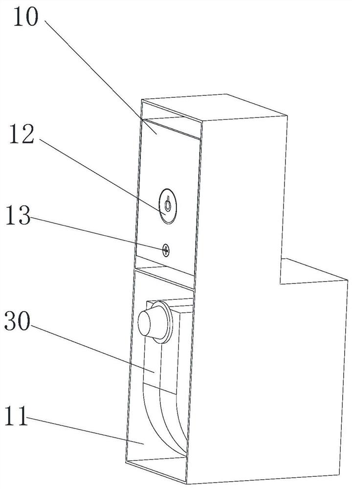
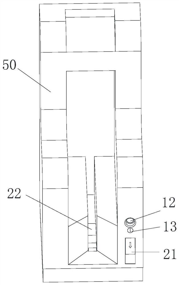
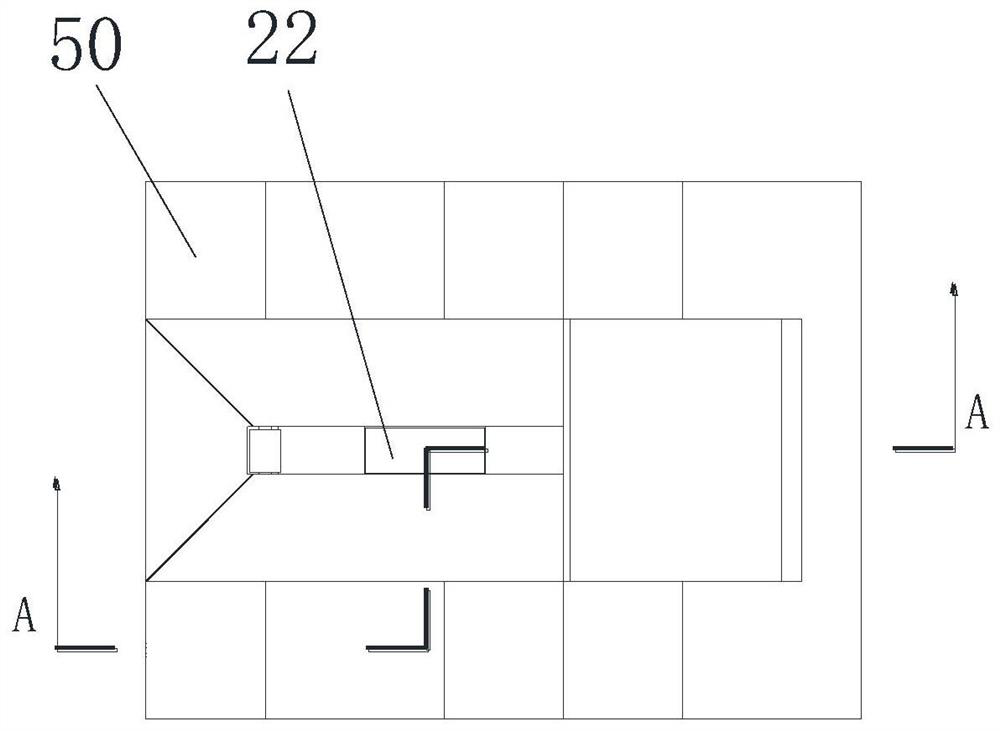
[0052] Such as Figures 1 to 14 A locking mechanism shown includes a housing 10, a baffle assembly 20, a lock bar assembly 30 and a lock body assembly 40 disposed in the housing 10, the housing 10 has an opening 11; the baffle assembly 20 has a baffle 21 , the baffle plate 21 is movably arranged at the opening 11 to close or open the opening 11; the locking bar assembly 30 can be accommodated in the housing 10, the locking bar assembly 30 has a locking bar 31, when the baffle plate 21 opens at least a part of the opening 11 At this time, a part of the locking bar 31 can protrude out of the housing 10 from the opening 11 ;
[0053] In this embodiment, the locking bar assembly 30 and the lock body assembly 40 are arranged in the housing 10, and the baffle plate 21 can close or open the opening 11. When the baffle plate assembly 20 moves and closes the opening 11, the locking bar of the locking bar assembly 30 31 is stopped in the housing 10, when the baffle 21 opens a part of t...
Embodiment 2
[0083] The difference from Embodiment 1 is that the baffle assembly 20 is different.
[0084] In this embodiment, the baffle assembly 20 includes a baffle 21, an inductor and a motor for sensing the position of the locked piece, the motor is connected with the baffle 21 and the sensor, and when the sensor detects that the locked piece is in the position to be locked After the position, the motor acts to drive the shutter 21 to open the opening 11 .
[0085] Specifically, an inductor is arranged on the baffle 21 or the housing 10, and the sensor can be an infrared sensor. When the bicycle arrives at a predetermined parking position, the inductive element senses the position of the bicycle and starts the motor, which drives the baffle 21 moves, so that the shutter 21 opens a part of the opening 11, so that the locking bar 31 can protrude from the opening 11. In the above method, the sliding of the baffle plate 21 is controlled by means of remote induction and motor transmission...
PUM
 Abstract
Description
Claims
Application Information