Paying-off device

The technology of a pay-off device and a threaded barrel is applied in the field of the pay-off device, which can solve the problems such as the inability to apply the long-length spool, the labor intensity of the staff, the single function of the pay-off rack, etc. , the effect of reducing friction

Inactive Publication Date: 2014-12-24
STATE GRID CORP OF CHINA +1
View PDF6 Cites 6 Cited by
  • Summary
  • Abstract
  • Description
  • Claims
  • Application Information

AI Technical Summary

Problems solved by technology

[0006] The purpose of the present invention is to overcome the disadvantages of the existing pay-off frame, such as single function, inability to adjust the height, inapplicability to wire reels with larger diameters and longer lengths, easy wear and tear, and high labor intensity of the staff, and to provide a pay-off rack. device

Method used


Image

  • Paying-off device
  • Paying-off device

Examples


Embodiment 1

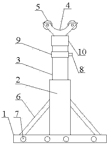
[0033] Such as figure 1 and figure 2 As shown, a pay-off device includes a base 1, an internally threaded cylinder 2, a screw rod 3, a Y-shaped bracket 4, a runner 5 and a fixed rod 6, the internally threaded cylinder 2 is arranged in the middle of the base 1, and the two fixed rods 6 The upper end is connected to the outer surface of the internally threaded cylinder 2, the lower ends of the two fixing rods 6 are connected to the two ends of the base 1 respectively, the screw rod 3 is arranged in the internally threaded cylinder 2 and threadedly connected with the internally threaded cylinder 2, and the Y-shaped bracket 4 is set On the top of the screw rod 3 , two runners 5 are symmetrically arranged on the top of the Y-shaped bracket 4 .

[0034] When the present embodiment is in use, two pay-off devices are used together. Place the two pay-off devices side by side, adjust the distance between the two pay-off devices, so that the rotating shafts at both ends of the reel ca...


PUM


Abstract

The invention discloses a paying-off device. The paying-off device comprises a base (1), an inner threaded barrel (2), a screw (3), a Y-shaped support (4), rotating wheels (5) and fixing rods (6), wherein the inner threaded barrel (2) is arranged in the middle of the base (1); the upper ends of the two fixing rods (6) are connected with the outer surface of the inner threaded barrel (2); the lower ends of the two fixing rods (6) are respectively connected to two ends of the base (1); the screw (3) is arranged in the inner threaded barrel (2) and is in threaded connection with the inner threaded barrel (2); the Y-shaped support (4) is arranged on the top of the screw (3); and the two rotating wheels (5) are symmetrically arranged on the top of the Y-shaped support (4). The paying-off device has the advantages that the paying-off device is suitable for wire coils with different lengths and different diameters; the friction force of the paying-off device is small when the paying-off device works; and the labor intensity of workers is reduced.

Description

technical field [0001] The invention relates to a tool for electric power construction, in particular to a pay-off device for carrying a cable reel. Background technique [0002] When the cables used in the power system leave the factory, in order to facilitate the transportation and storage of the cables, they are all wound on the spools. When the cable is put into use, the cable needs to be pulled out from the reel. At this time, in order to prevent the reel from rolling, the reel needs to be fixed. [0003] At present, pay-off racks are mainly used to fix the wire reels, that is, the rotating shafts at both ends of the wire reels are placed on the pay-off racks. When the cables are pulled out, the wire reels will rotate on the pay-off racks, thereby avoiding the wire reel on the bottom surface. A scrolling situation occurs. [0004] However, the existing pay-off stand has a single function and cannot be adjusted in height. For some reels with larger diameters and longer...

Claims


Application Information

Patent Timeline
Patent Type & Authority Applications(China)
IPC IPC(8): B65H49/32
Inventor 李涛张剑韦皓张续沈艾
Owner STATE GRID CORP OF CHINA
Why Eureka
Try Eureka