Energy storage apparatus for the preheating of feed water

A technology of energy storage and feed water preheater, applied in feed water heaters, lighting and heating equipment, preheating, etc., can solve problems such as deficiencies, and achieve the effect of ensuring process stability and process safety

Inactive Publication Date: 2014-12-24
SIEMENS AG
View PDF0 Cites 4 Cited by
  • Summary
  • Abstract
  • Description
  • Claims
  • Application Information

AI Technical Summary

Problems solved by technology

However, an effective heat transfer for steam production may therefore be insufficient because of the large amount of water introduced into the water-steam circuit

Method used


Image

  • Energy storage apparatus for the preheating of feed water

Examples


Embodiment Construction

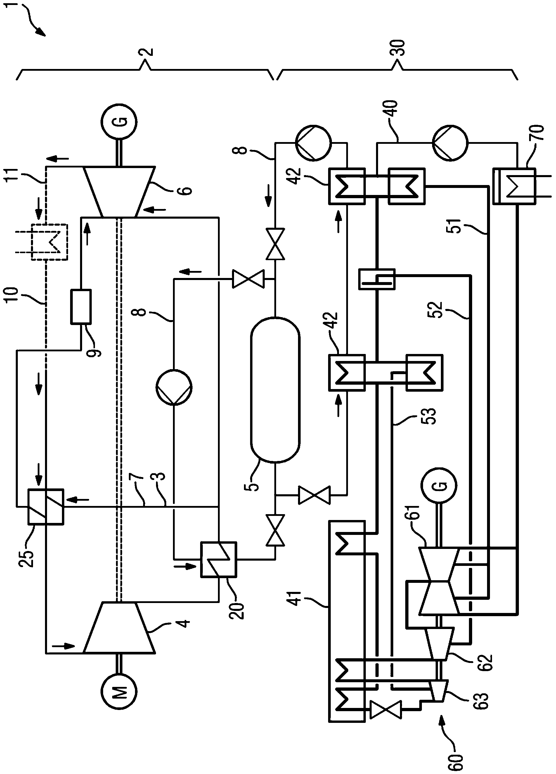
[0028] figure 1 An embodiment of an energy storage device 1 according to the invention for storing thermal energy is shown. The energy storage device 1 has a charging cycle 2 and a discharging cycle 30 . Charging cycle 2 includes a compressor 4 coupled to a motor M via a mechanical shaft. Furthermore, charging cycle 2 has an expansion turbine 6 which is mechanically coupled to a generator G for generating electrical energy. The compressor 4 and the expansion turbine 6 are fluidically connected to one another via a first line 7 for the first working gas 3 . Furthermore, a first heat exchanger 20 is connected in the first line 7 , which enables heat transfer from the first line 7 to the heat store 5 . In this case, the first heat exchanger 20 is connected on the primary side to the first line 7 and on the secondary side to the second line 8 .

[0029] Now, if the compressor 4 is driven by the motor M in normal operation, the first working gas 3 sucked into the compressor 4 i...


PUM


Abstract

The invention relates to an energy storage apparatus for the storage of thermal energy. The energy storage apparatus is equipped with a charging circuit, having a compressor, a heat store and an expansion turbine, the compressor connected on the outlet side to the inlet of the expansion turbine via a first pipe for a first working gas, and the heat store inserted into a second pipe, and the first pipe connected to a first heat exchanger, by means of which the first pipe and the second pipe are coupled in thermal thechnology, and, furthermore, having a discharge circuit which has a water / steam circuit equipped with a steam generator and which has at least one feed water preheater preceding the steam generator with respect to the direction of flow of the water in this water / steam circuit, and thermal coupling between the charging circuit and discharge circuit achieved by the feed water preheater, in particular achieved solely by the feed water preheater.

Description

technical field [0001] The invention relates to an energy storage device for storing thermal energy with a charging and discharging cycle, which is suitable for preheating feedwater in a hot water-steam cycle. Such energy storage devices are preferably integrated in power plants. Background technique [0002] Due to the increasing supply of electrical energy from renewable energy sources in power distribution networks, the need to be able to temporarily store electrical energy over time increases. Here, the aim is that electrical energy can be drawn from the current distribution network in the event of an oversupply, and that use at a later time can cause the current distribution network to use this electrical energy again, thereby stabilizing the current distribution network. [0003] The approach taken in the technical literature is to convert the available electrical energy into thermal energy and to temporarily store this thermal energy over time. When additional elect...

Claims


Application Information

Patent Timeline
Patent Type & Authority Applications(China)
IPC IPC(8): F01K3/00F22D1/00
CPCF01K3/00F01K7/22F01K7/40F01K23/02Y02E20/16F01B25/00
Inventor C.布伦胡伯C.格雷伯G.齐默曼
Owner SIEMENS AG
Why Eureka
Try Eureka