Ball valve

A technology of ball valves and ball cores, which is applied in the direction of valve devices, cocks including cut-off devices, engine components, etc. It can solve problems such as difficulty in ensuring the reliability of bidirectional sealing, internal leakage of valves, wear of the ball core and the lower side of the sealing valve seat, etc.

Inactive Publication Date: 2014-12-24
YANKE SHANGHAI VALVE IND CO LTD
View PDF5 Cites 8 Cited by
  • Summary
  • Abstract
  • Description
  • Claims
  • Application Information

AI Technical Summary

Problems solved by technology

However, the existing seated ball valves have the following problems: first, the tight fit between the sealed valve seat and the auxiliary valve body, since there is no elastic piece between the two, it will inevitably cause the medium to flow in the reverse direction. The ball core will have a relative movement with the thrust direction of the medium, and the main sealing valve seat does not have a compensating force to make up for this moving distance, so there will inevitably be a gap between the contact surface of the ball core and the sealing valve

Method used


Image

  • Ball valve
  • Ball valve

Examples


Embodiment Construction

[0012] A preferred embodiment will be given below, and the present invention will be described more clearly and completely in conjunction with the accompanying drawings.

[0013] The structure of the ball valve of the present embodiment is as follows:

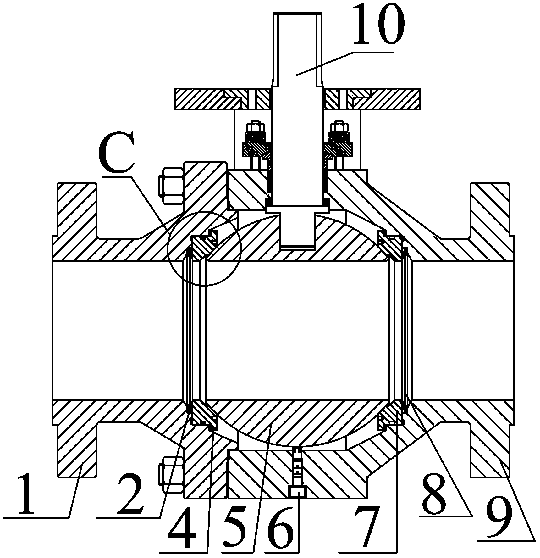
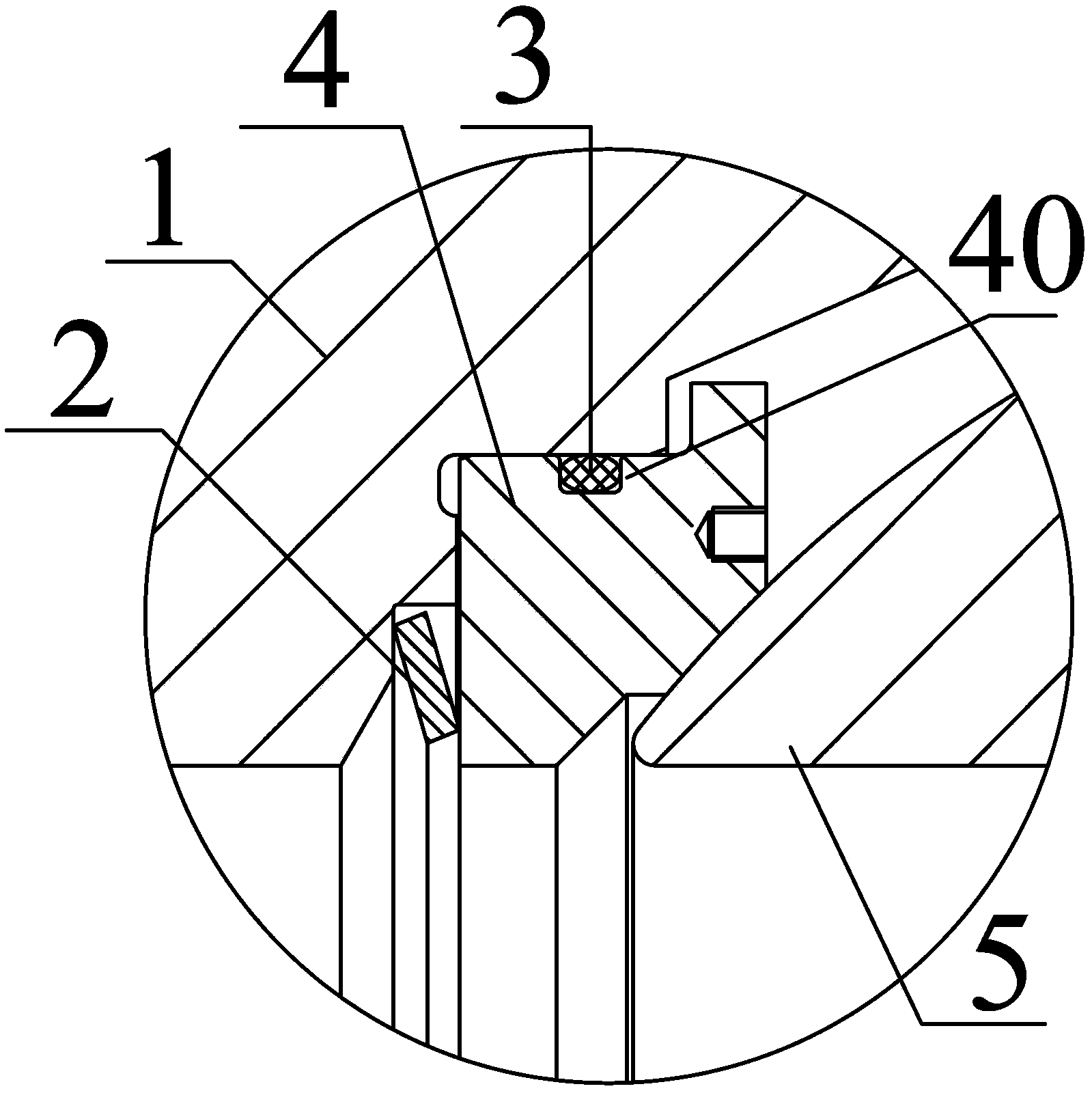
[0014] Please combine figure 1 It should be understood that the ball valve of this embodiment includes an auxiliary valve body 1, a first sealing valve seat 4, a ball core 5, a second sealing valve seat 7 and a main valve body 9, the auxiliary valve body 1 and the main valve body The valve bodies 9 are connected to each other, the first sealing valve seat 4, the ball core 5 and the second sealing valve seat 7 press against each other in sequence, and are arranged in the cavity formed by the auxiliary valve body 1 and the main valve body 9 A first elastic member 2 is arranged between the auxiliary valve body 1 and the first sealing valve seat 4 , and a second elastic member 8 is arranged between the second sealing valve seat 7 ...


PUM


Abstract

The invention discloses a ball valve which comprises an auxiliary valve body, a first sealing valve seat, a ball core, a second sealing valve seat and a main valve body. The auxiliary valve body and the main valve body are connected with each other, the first sealing valve seat, the ball core and the second sealing valve seat are sequentially mutually abutted and are arranged in a chamber formed by the auxiliary valve body and the main valve body, a first elastic piece is arranged between the auxiliary valve body and the first sealing valve seat, and a second elastic piece is arranged between the second sealing valve seat and the main valve body. The first elastic piece and the second elastic piece cooperatively push the first sealing valve seat and the second sealing valve seat to shift with the ball core, and the first sealing valve seat and the second sealing valve seat are still capable of being abutted and sealed on the surface of the ball core, so that clearance cannot be formed in the valve bodies, inner leakage never occurs, and particles cannot be embedded in the ball core to cause abrasion of the ball core.

Description

technical field [0001] The invention relates to the field of valve bodies, in particular to a ball valve. Background technique [0002] Due to its many advantages, ball valves are widely used in petroleum, chemical, natural gas, electric power, metallurgy and other industries. However, the existing seated ball valves have the following problems: first, the tight fit between the sealed valve seat and the auxiliary valve body, since there is no elastic piece between the two, it will inevitably cause the medium to flow in the reverse direction. The ball core will have a relative movement with the thrust direction of the medium, and the main sealing valve seat does not have a compensating force to make up for this moving distance, so there will inevitably be a gap between the contact surface of the ball core and the sealing valve seat that is sufficient for the medium to enter. The gap not only leads to the internal leakage of the valve body, but also accelerates the wear betwe...

Claims


Application Information

Patent Timeline
IPC IPC(8): F16K5/20F16K5/08F16K5/06
CPCF16K5/06F16K5/08F16K5/20
Inventor 夏传宝陈大军陈涛陈维
Owner YANKE SHANGHAI VALVE IND CO LTD
Why Eureka
Try Eureka