A shell leak test fixture

A leak test and fixture technology, which is applied in the direction of measuring the acceleration and deceleration rate of the fluid and using the liquid/vacuum degree for liquid tightness measurement, etc. Achieve the effect of ensuring sealing performance, high degree of automation, and accurate positioning and clamping

Active Publication Date: 2017-01-25
HENAN FEILONG WUHU AUTOMOBILE PARTS
View PDF6 Cites 4 Cited by
  • Summary
  • Abstract
  • Description
  • Claims
  • Application Information

AI Technical Summary

Problems solved by technology

The effect of the shell airtightness test will also be affected by the structure of the clamping equipment. The design of the sealing link of the traditional airtightness test equipment is not reasonable enough, resulting in leakage at the seal after the shell is clamped, resulting in misjudgment. Affect the pass rate of the product

Method used


Image

  • A shell leak test fixture
  • A shell leak test fixture
  • A shell leak test fixture

Examples


Embodiment Construction

[0014] In order to make the technical means, creative features, goals and effects achieved by the present invention easy to understand, the present invention will be further elaborated below.

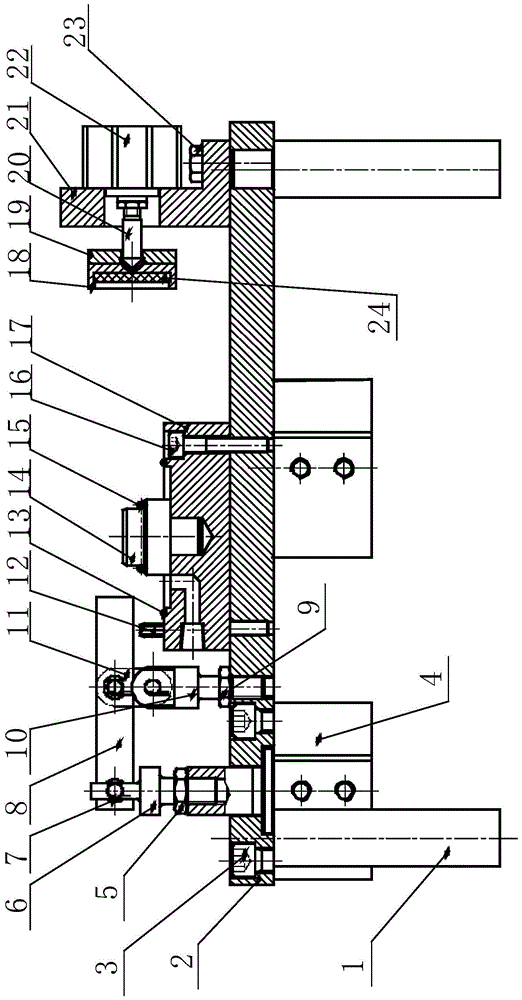
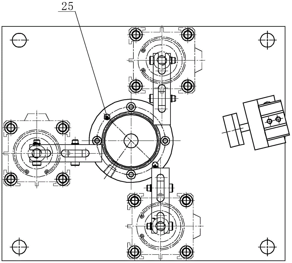
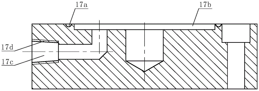
[0015] Such as Figure 1 to Figure 3 As shown, a shell leak test fixture includes a column 1 and a clamp body 2 installed on the upper end of the column 1. The front, rear and left parts of the clamp body 2 are equipped with pneumatic compression devices. The middle part of the concrete body 2 is equipped with a supporting positioning device, and the right part of the clamp body 2 is equipped with a mouth sealing device. Place the shell to be tested on the support and positioning device, then start the pneumatic clamping device to clamp, then start the sealing device to block the water inlet of the shell, and finally use the external equipment to fill the gap between the shell and the support and positioning device. Gas is injected into the sealed cavity to realize the purpose of testi...


PUM


Abstract

The invention relates to a shell leakage testing clamp. The shell leakage testing clamp comprises stand columns and a clamp body arranged at the upper ends of the stand columns. Pneumatic pressing devices are arranged on the front portion, the rear portion and the left portion of the clamp body respectively. A supporting and positioning device is arranged in the middle of the clamp body. A nozzle sealing device is arranged on the right portion of the clamp body. The shell leakage testing clamp has the advantages of being reasonable in structural design, high in automation degree, convenient to operate and regulate and the like, can rapidly clamp and position an automobile water pump shell, and is high in operation efficiency and accurate in positioning and clamping accuracy; the sealing performance of the sealing position is ensured, and therefore detection quality can be improved, and the possibility of wrong detection can be lowered.

Description

technical field [0001] The invention relates to an auxiliary device for testing the leak-tightness of a water pump casing, in particular to a casing leakage test fixture. Background technique [0002] In the cylinder block of the car engine, there are many water channels for cooling water circulation, which are connected with the radiator placed in the front of the car, commonly known as the water tank, through water pipes to form a large water circulation system. The upper water outlet of the engine is equipped with A water pump, driven by the fan belt, pumps out the hot water in the water channel of the engine block and pumps in the cold water. There is also a thermostat next to the water pump. When the car is just started and the car is cold, it is not turned on, so that the cooling water does not pass through the water tank, but only circulates in the engine. It is commonly known as a small cycle. When it is turned on, the hot water in the engine is pumped into the wate...

Claims


Application Information

Patent Timeline
Patent Type & Authority Patents(China)
IPC IPC(8): G01M3/32
Inventor 张锋何田闫飞
Owner HENAN FEILONG WUHU AUTOMOBILE PARTS
Why Eureka
Try Eureka