
Common positioning fixture for CNC milling machine

A general-purpose positioning, CNC milling machine technology, applied in positioning devices, clamping, manufacturing tools, etc., can solve the problems of workpiece deformation, affecting work efficiency, easy to pinch workpieces, etc., to achieve fast clamping positioning, reduce tool setting times, Ensure the effect of processing quality

Active Publication Date: 2018-10-12
重庆拓菱汽车配件有限责任公司
View PDF9 Cites 5 Cited by
  • Summary
  • Abstract
  • Description
  • Claims
  • Application Information

AI Technical Summary

Problems solved by technology

[0002] At present, most of the existing CNC milling machines use vises as universal fixtures, and use vises to clamp various types of workpieces on the workbench of CNC milling machines for processing, while existing vises often use a fixed clamp block The movable clamping block is used to complete the clamping of the workpiece. When processing different workpieces, the coordinate system of the CNC milling machine is different. Before processing different workpieces, tool setting is required to determine the coordinate system. The tool setting of the CNC milling machine takes up a lot of time. time, which seriously affects the work efficiency, and when clamping soft workpieces such as aluminum materials with vises, it is easy to pinch the workpiece, causing local deformation of the workpiece and affecting the processing quality

Method used


Image

  • Common positioning fixture for CNC milling machine
  • Common positioning fixture for CNC milling machine
  • Common positioning fixture for CNC milling machine

Examples


Embodiment Construction

[0016] Below in conjunction with specific embodiment, further illustrate the present invention. It should be understood that these examples are only used to illustrate the present invention and are not intended to limit the scope of the present invention. In addition, it should be understood that after reading the content taught by the present invention, those skilled in the art may make various changes or modifications to the present invention, and these equivalent forms also fall within the scope defined in the present application.

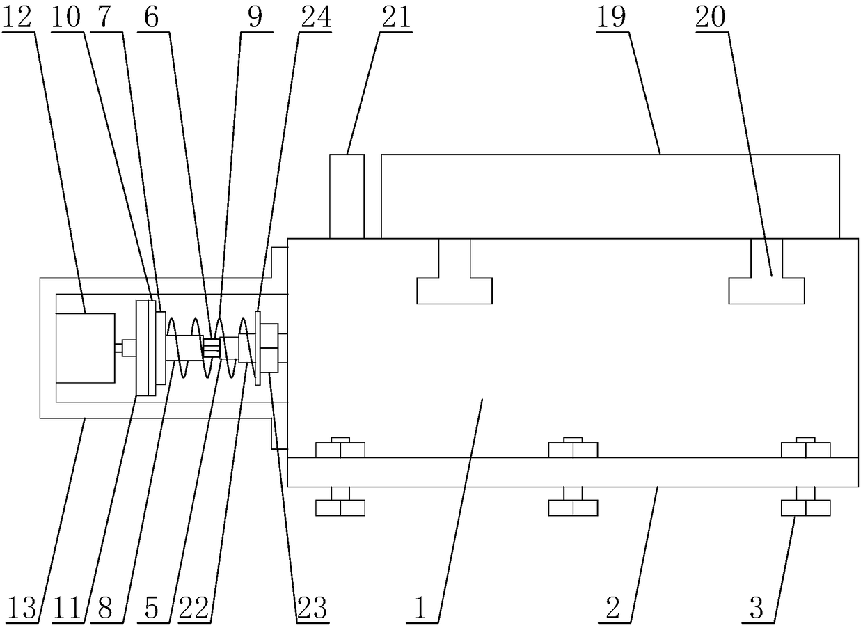
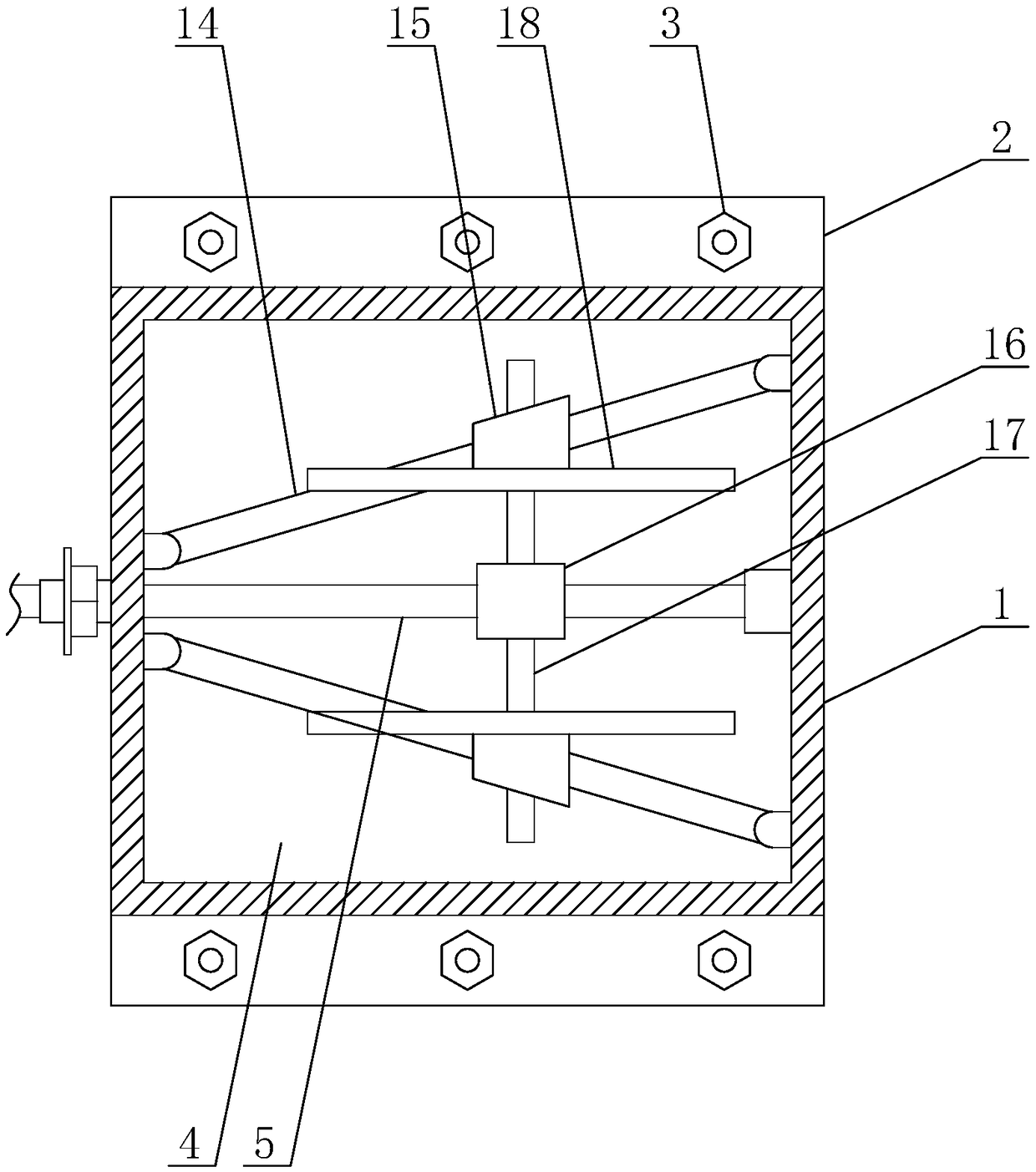
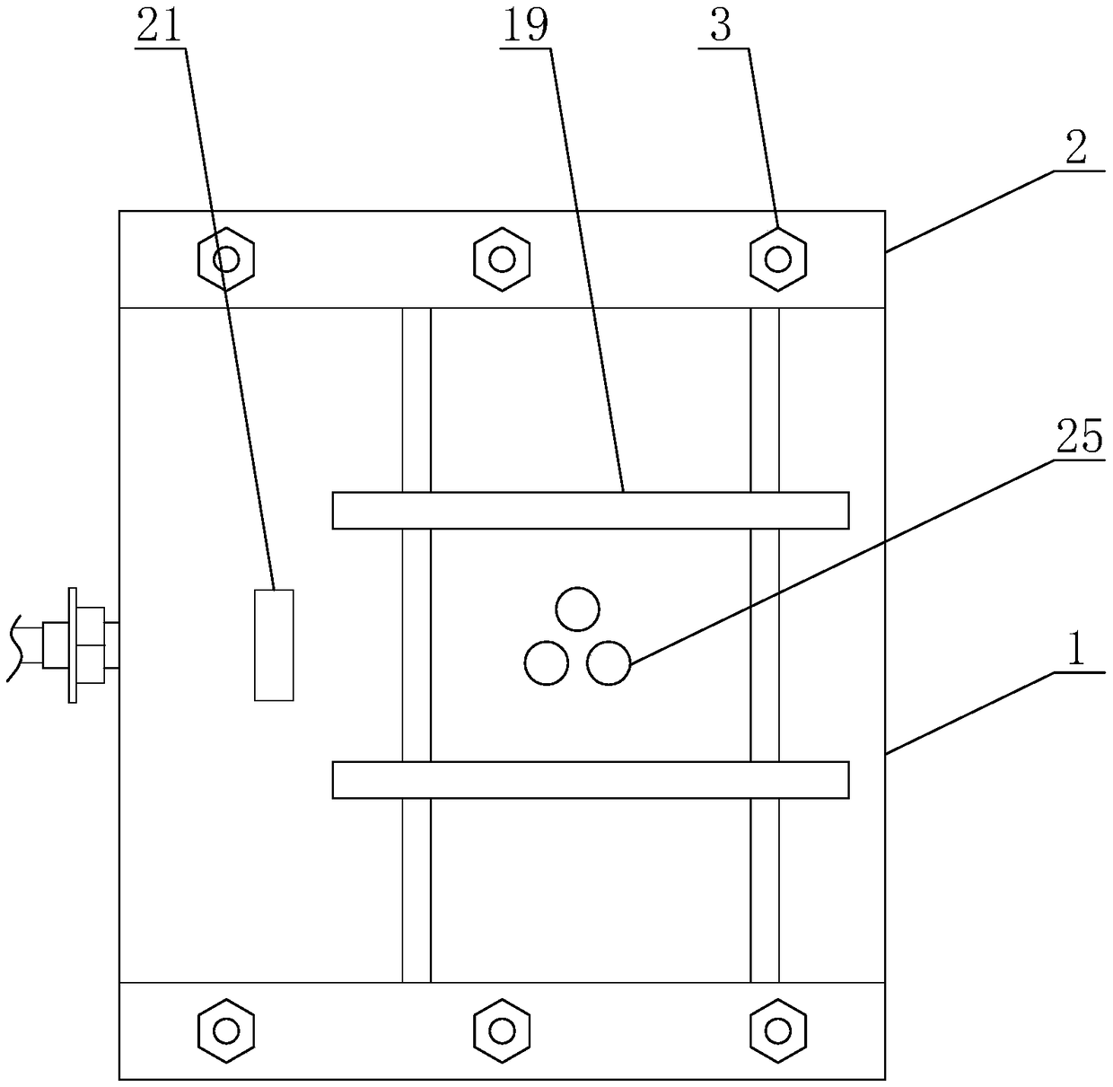
[0017] The present invention is a general positioning fixture for CNC milling machine, including a base 1, the bottom of both ends of the base 1 is provided with a connecting plate 2, and the connecting plate 2 is provided with a connecting screw 3, through which the connecting screw 3 of the present invention Installed on the table of CNC milling machine. The bottom of described base 1 is provided with cavity 4, and the middle part in describe...


PUM


Abstract

The invention discloses a common positioning fixture for a CNC milling machine, and mainly relates to the field of mechanical manufacturing. The common positioning fixture comprises a base, a cavity is arranged at the bottom of the base, a lead screw is arranged at the middle portion of the interior of the cavity, a spline shaft is arranged at the end, extending out of the base, of the lead screw,the two sides of the lead screw are provided with inclined supporting rods, sliding blocks are arranged on the inclined supporting rods, a nut is arranged on the lead screw, guide rods are arranged on the two sides of the nut, the sliding blocks are provided with penetration holes matched with the guide rods, a vertical plate is vertically arranged on the tops of the sliding blocks, a clamping block is arranged on the side, close to the lead screw, of the vertical plate, T-shaped sliding blocks are symmetrically arranged at the bottom of the clamping block, the bottom faces of the T-shaped sliding blocks and the top faces of the sliding blocks are located on one horizontal face, and a positioning block is arranged at the end between the two clamping blocks. The common positioning fixturehas the beneficial effects that workpiece clamping and positioning can be quickly completed, the tool setting time number can be reduced, workpiece extrusion is avoided, the machining quality is guaranteed, and the working efficiency is improved.

Description

technical field [0001] The invention relates to the field of mechanical manufacturing, in particular to a universal positioning fixture for a numerically controlled milling machine. Background technique [0002] At present, most of the existing CNC milling machines use vises as universal fixtures, and use vises to clamp various types of workpieces on the workbench of CNC milling machines for processing, while existing vises often use a fixed clamp block The movable clamping block is used to complete the clamping of the workpiece. When processing different workpieces, the coordinate system of the CNC milling machine is different. Before processing different workpieces, tool setting is required to determine the coordinate system. The tool setting of the CNC milling machine takes up a lot of time. The time has seriously affected the work efficiency, and when clamping soft workpieces such as aluminum materials with vises, it is easy to pinch the workpiece, causing local deformat...

Claims


Application Information

Patent Timeline
IPC IPC(8): B23Q3/06B23Q3/18
Inventor 温晓妮于海青
Owner 重庆拓菱汽车配件有限责任公司
Learn More