
Roller rolling press pump

A roller and rolling technology, applied in the field of roller rolling pumps, can solve the problems of rollers on one side of the raceway, troublesome use, inconvenient opening and closing, etc., and achieve fast clamping and positioning, easy manufacturing and convenient operation. Effect

Inactive Publication Date: 2007-08-15
张浩
View PDF0 Cites 5 Cited by
  • Summary
  • Abstract
  • Description
  • Claims
  • Application Information

AI Technical Summary

Problems solved by technology

[0003] The existing small or miniature roller roller pump pump body generally cannot be opened, and some of the roller roller pump pumps that can be opened use the pump body and the pump body slider to be hinged from the side, and then fixed with connectors after closing. Some pump bodies and pump body sliders do not need to be hinged but are directly connected by connectors, which is quite inconvenient to open and close. What is more problematic is that sometimes the connectors may be loosened and displaced, causing the rollers to deviate from the raceway. side
In addition, most of the gaps between the rollers and the pump body of the existing small or miniature rolling pumps cannot be adjusted. A few can be adjusted by manually adjusting the thread to adjust the gap between the rollers and the pump body. The disadvantage is that it is troublesome to use. , The symmetry of the two rollers is not good

Method used


Image

  • Roller rolling press pump
  • Roller rolling press pump

Examples


Embodiment Construction

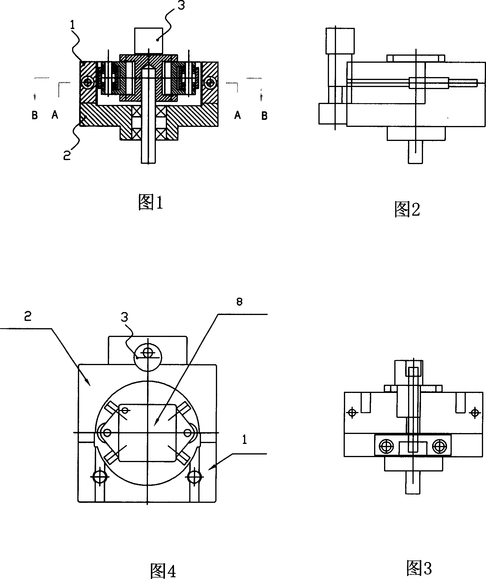
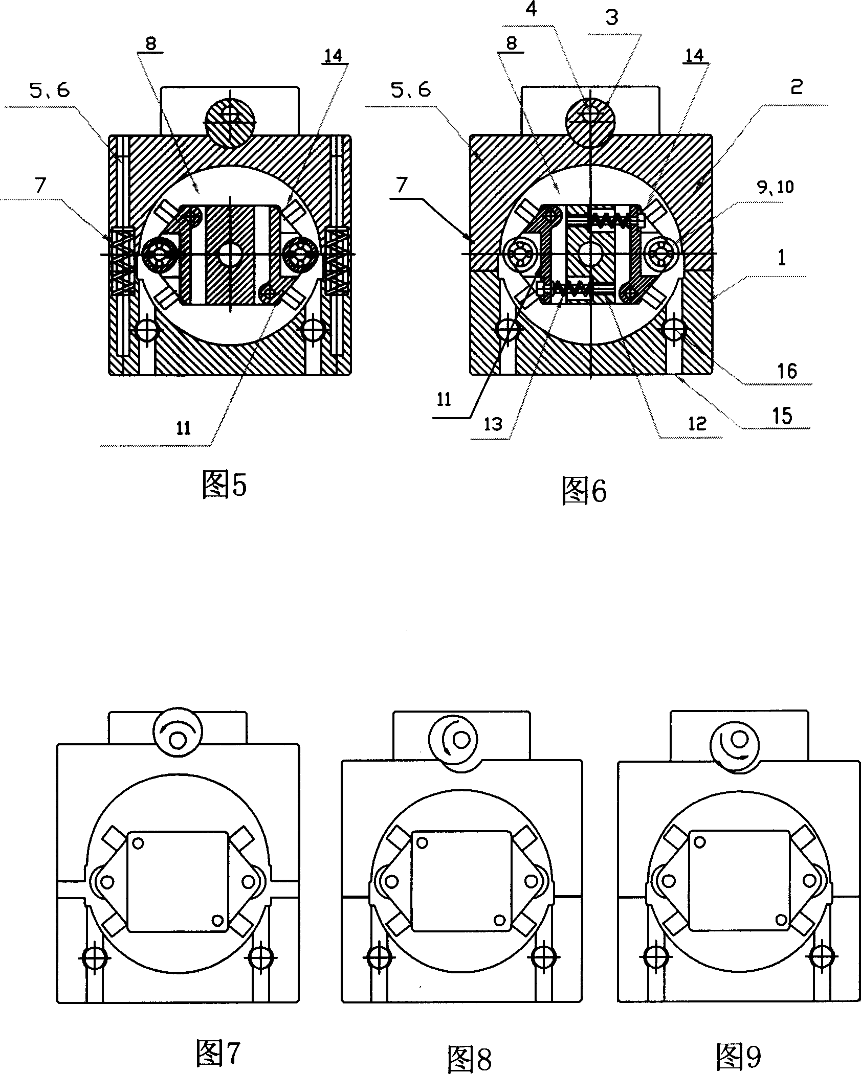
[0028] The present invention will be described in further detail below in conjunction with accompanying drawing and embodiment:

[0029] The roller rolling pump of the present invention shown in Fig. 1 to Fig. 6 is composed of a split pump body 1, a pump body slider 2 and a pump core assembly 3, and the pump body slider 2 is opened in the middle of one side of a rectangular block. There is a semicircular notch. The pump body 1 is a stepped rectangular block. There is a corresponding semicircular notch in the middle of the upper part. After the two cooperate to form a round hole, the side of the semicircular hole of the pump body slider becomes a raceway. The pump body There are also conduit inlet and outlet holes 15 and conduit fixing columns 16 on the top; on the pump body joint surface combined with the pump body slider, there are protruding slider guide rods 5, and on the joint surface of the pump body slider, there is a There is a corresponding slider guide rod hole 6, the...


PUM


Abstract

The invention relates to a small roller pump comprising a pump body 1, a block 2, and a pump element 8. The body and the block are locked and opened by a positioning eccentric wheel 3, arranged on a positioning base relative to the back of the block. The distance between the body and the block is smaller than two timed eccentric distance of the eccentric wheel, the back of the block is disposed with an arc cut relative to the positioning eccentric wheel, the body combine face combined with the block is arranged with a block guiding rod (5) protruded, and the combine face of the block is disposed with relative block guiding rod hole (6), engaged with the rod (5), the block guiding rod is sheathed with a block spring (7), the roller swing support (11), swing stop rod (12) and swing spring (13) form a self-elastic space adjuster of roller to automatically adjust the space between the roller and the inner wall of the pump, and limit the minimum space. The invention has simple structure, easy production and simple operation or the like.

Description

technical field [0001] The invention relates to a roller rolling pump, in particular to a small roller rolling pump used in medical equipment. Background technique [0002] Roller roller pump is widely used in the human body or other fields to complete the non-polluting transportation of blood, medicinal liquid and liquid. It is a mature, reliable, high-precision, fully isolated non-polluting liquid transportation equipment. The outer wall of the soft pump tube with elastic function silicone rubber or other plastics is rolled to realize the pollution-free delivery of the liquid in the pipeline. The main structure and working principle of the roller rolling pump is: the rolling pump is composed of the pump body and the pump body slider. There is a rolling groove raceway in the pump, and the pump core assembly is supported in the groove, and the pump core assembly is mounted on the periphery. There are axial rollers, and there is a gap between the rollers and the rolling groo...

Claims


Application Information

Patent Timeline
Patent Type & Authority Applications(China)
IPC IPC(8): F04B43/12
Inventor 张浩
Owner 张浩
Learn More