A deployment mechanism and an umbrella-shaped antenna reflector with the deployment mechanism

A technology for deploying mechanisms and umbrella antennas, applied to antennas, electrical components, etc., can solve problems such as difficulties, large volume and weight of umbrella antenna reflectors, and achieve low cost, light weight, and small volume

Active Publication Date: 2017-01-25
SHANGHAI YS INFORMATION TECH
View PDF7 Cites 0 Cited by
  • Summary
  • Abstract
  • Description
  • Claims
  • Application Information

AI Technical Summary

Problems solved by technology

However, the bulky and heavy deployment mechanism would lead to excessive volume and weight of the umbrella antenna reflector, making it difficult to transport the umbrella antenna reflector into space by rocket

Method used


Image

  • A deployment mechanism and an umbrella-shaped antenna reflector with the deployment mechanism
  • A deployment mechanism and an umbrella-shaped antenna reflector with the deployment mechanism
  • A deployment mechanism and an umbrella-shaped antenna reflector with the deployment mechanism

Examples


Embodiment Construction

[0033] The advantages of the present invention will be further elaborated below in conjunction with the accompanying drawings and specific embodiments.

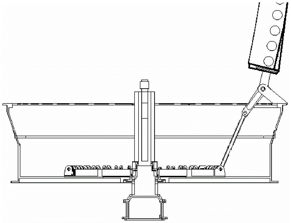
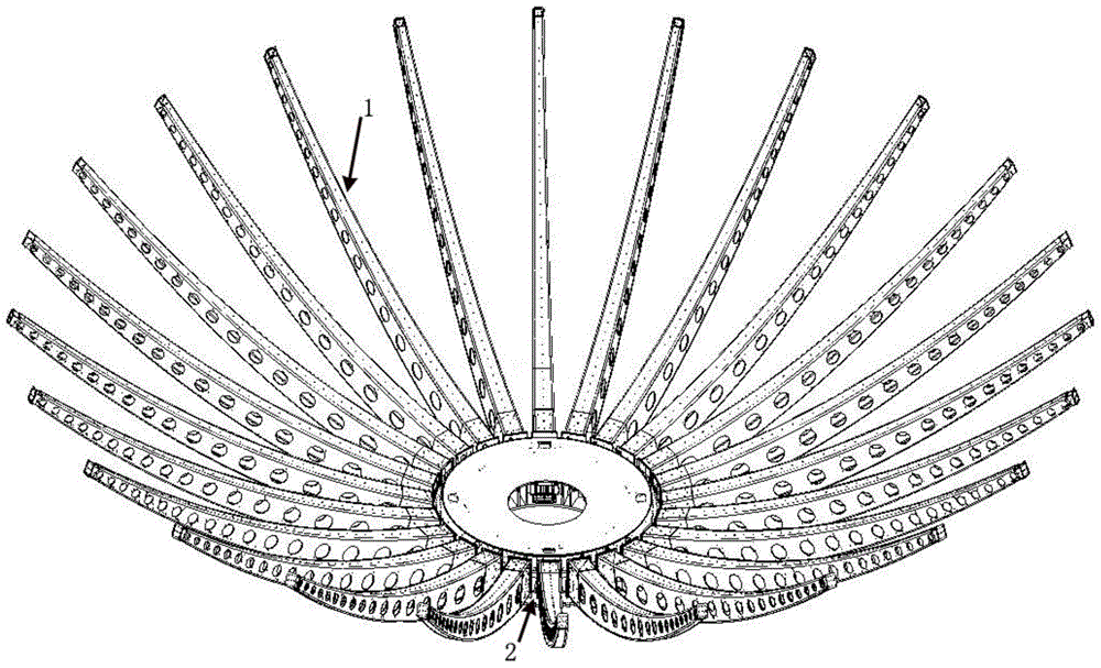
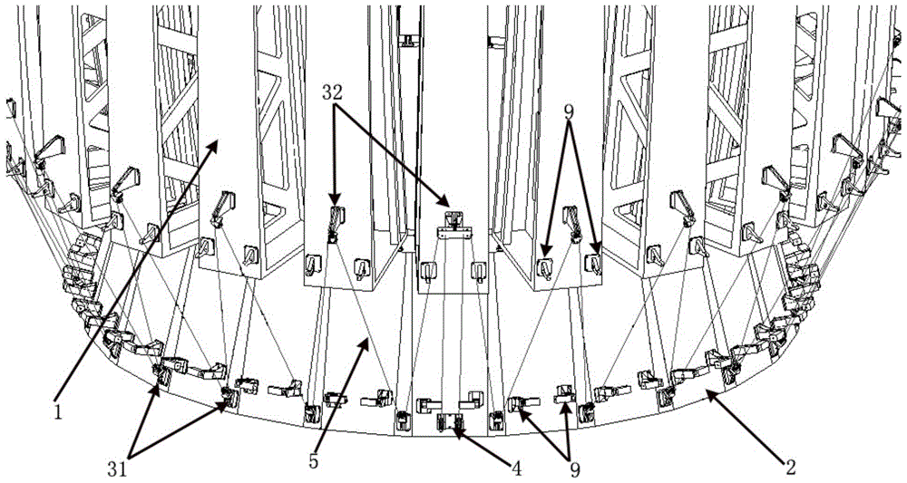
[0034] like figure 2 As shown, the umbrella antenna reflector mainly includes components such as a base, a solid surface reflector, a spreading rib 1, and a spreading mechanism. One side of the base is fixed on the antenna support (not shown), and the other side is fixed to the solid surface reflector. Between the two sides is the outer edge 2 of the base. The outer edge 2 of the base is preferably cylindrical Edge or polygon edge. The expansion rib 1 includes a top and a root, the cross-section of the root is larger than that of the top, and the roots of the expansion rib 1 are hingedly connected with the outer edge 2 of the base, so that each expansion rib 1 can go around the root and the outside of the base. Edge 2 unfolds at the hinged position. like image 3 and Figure 4 As shown, the deployment mechanism of the p...


PUM


Abstract

The invention provides an unfolding mechanism applied to an umbrella-shaped antenna reflector. The antenna reflector comprises a base and unfolding ribs. The unfolding ribs are connected with the outer side edge of the base through hinges. The unfolding mechanism comprises motors and power cables connected with the motors, the motors are located below the roots of the unfolding ribs and fixedly connected to the outer side edge of the base, the unfolding ribs are connected with the outer side edge of the base through the power cables, and when the power cables are tightened by driving the motors, the unfolding ribs rotate around the connecting position of the hinges through the power cables, and therefore the unfolding ribs can be unfolded. The unfolding mechanism has the advantages of being small in size, light in weight, low in cost and good in unfolded effect. The invention further provides the umbrella-shaped antenna reflector with the unfolding mechanism.

Description

technical field [0001] The present invention relates to an unfolding mechanism, and also relates to an umbrella-shaped antenna reflector with the unfolding mechanism. Background technique [0002] The umbrella-shaped antenna reflector used in space needs to expand the expansion ribs to form a complete reflection surface after reaching a predetermined position. Rotating the deployment ribs of the umbrella antenna reflector from the retracted state to the fully deployed state is achieved by the deployment mechanism. In the prior art, the deployment mechanism of the umbrella-shaped antenna reflector generally adopts an axisymmetric multi-link mechanism. A typical link mechanism such as the deployment mechanism of the US data relay satellite TDRS, its specific structure is as follows figure 1 shown. The working principle of this axisymmetric connecting rod deployment mechanism is: under the side effect of the drive assembly and screw transmission, the slider moves up and down...

Claims


Application Information

Patent Timeline
Patent Type & Authority Patents(China)
IPC IPC(8): H01Q15/14
Inventor 万小平马小飞张欣武勇斌
Owner SHANGHAI YS INFORMATION TECH
Why Eureka
Try Eureka