Permanent magnet synchronous motor

A permanent magnet synchronous motor and permanent magnet technology, which can be used in motors, electromechanical devices, electric vehicles, etc., can solve the problems of high vehicle cost and large built-in space occupied by the power system, and achieve the effect of reducing occupied space and reducing costs.

Active Publication Date: 2014-12-24
GREAT WALL MOTOR CO LTD
View PDF5 Cites 5 Cited by
  • Summary
  • Abstract
  • Description
  • Claims
  • Application Information

AI Technical Summary

Problems solved by technology

[0005] In view of this, the present invention aims to propose a permanent magnet synchronous motor to solve the problems that the power system of a hybrid vehicle in the prior art needs to be equipped with two motors, resulting in high vehicle cost and a large built-in space occupied by the power system

Method used


Image

  • Permanent magnet synchronous motor
  • Permanent magnet synchronous motor
  • Permanent magnet synchronous motor

Examples


Embodiment Construction

[0034] It should be noted that the embodiments of the present invention and the features in the embodiments can be combined with each other if there is no conflict. Hereinafter, the present invention will be described in detail with reference to the drawings and in conjunction with the embodiments.

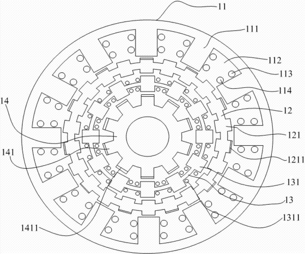
[0035] See figure 1 , The embodiment of the present invention provides a permanent magnet synchronous motor, which includes an annular stator core 11, an intermediate rotor 12, an adjusting rotor 13, an inner rotor 14 and a magnetic suspension bearing (not shown in the figure). The magnetic suspension bearing is used to position the intermediate rotor 12 and adjust the axial direction of the rotor 13. The stator core 11 has a plurality of first teeth 111 and a plurality of first teeth 111 separated by a plurality of first teeth 111 on the circumference of the stator core 11 in the radial inward direction. In the first slot 112, the drive winding 113 and the control winding 114 are se...


PUM


Abstract

The invention provides a permanent magnet synchronous motor which comprises a stator iron core, a middle rotor, an adjusting rotor, an inner rotor and a magnetic suspension bearing. The stator iron core is provided with a first toothed groove. A drive winding and a control winding are disposed in the first toothed groove. A certain air gap is formed between the middle rotor and each first tooth. The middle rotor comprises second teeth provided with first permanent magnets. The N pole of each first permanent magnet point outwardly, and the S pole thereof points inwardly. The adjusting rotor is located on the inner side of the middle rotor. A certain air gap is formed between the middle rotor and the adjusting rotor. The adjusting rotor comprises third teeth. The bottom end of each third tooth is opposite to the inner rotor. Adjusting rotor windings are disposed among the third teeth. The inner rotor is located on the inner side of the middle rotor. A certain air gap is formed between the middle rotor and the inner rotor. The inner rotor comprises fourth teeth provided with second permanent magnets. By the permanent magnet synchronous motor, the problems that the power system of a hybrid power car in the prior art needs to be equipped with two motors, cost of the whole car is high, and the power system occupies large space are solved.

Description

Technical field [0001] The present invention relates to the technical field of motors, in particular to a permanent magnet synchronous motor. Background technique [0002] At this stage, hybrid vehicles and electric vehicles are becoming more and more popular. Electric motors are needed in hybrid or electric vehicles. The earliest used was the DC motor system driven by the motor alone, but the DC motor system had the disadvantages of high quality and low efficiency, and required regular maintenance, and the failure rate was relatively high. Therefore, with the development of electronic power technology and digital technology, people began to apply asynchronous motors, permanent magnet synchronous motors or switched reluctance motors. Among them, permanent magnet synchronous motors have good reliability and are widely used. [0003] In the power system of a hybrid electric vehicle, it includes two motors, namely, a BSG motor (Belt-driven Starter Generator) connected to the engine...

Claims


Application Information

Patent Timeline
Patent Type & Authority Applications(China)
IPC IPC(8): H02K16/00H02K1/14H02K1/24H02K1/16H02K1/27
CPCY02T10/64
Inventor 刘宁安振徐亮王海洋马梦洁邓立军魏松孟伟颜广博翁浩宇
Owner GREAT WALL MOTOR CO LTD
Why Eureka
Try Eureka