CT (Computed Tomography) data compression method

A data compression and data technology, applied in the fields of digital video signal modification, electrical components, image communication, etc., can solve the problems of high compression speed, inability to take into account the compression ratio, low compression ratio, etc., to achieve the effect of improving the compression ratio

Active Publication Date: 2014-12-24
重庆真测科技股份有限公司
View PDF3 Cites 7 Cited by
  • Summary
  • Abstract
  • Description
  • Claims
  • Application Information

AI Technical Summary

Problems solved by technology

However, the existing lossless compression methods still have the problem of relatively low compression ratio, lack of pertinence, and cannot meet the requirements of industrial CT data transmission and storage.
[0004] The existing technical solutions are ma

Method used


Image

  • CT (Computed Tomography) data compression method
  • CT (Computed Tomography) data compression method

Examples


Embodiment 1

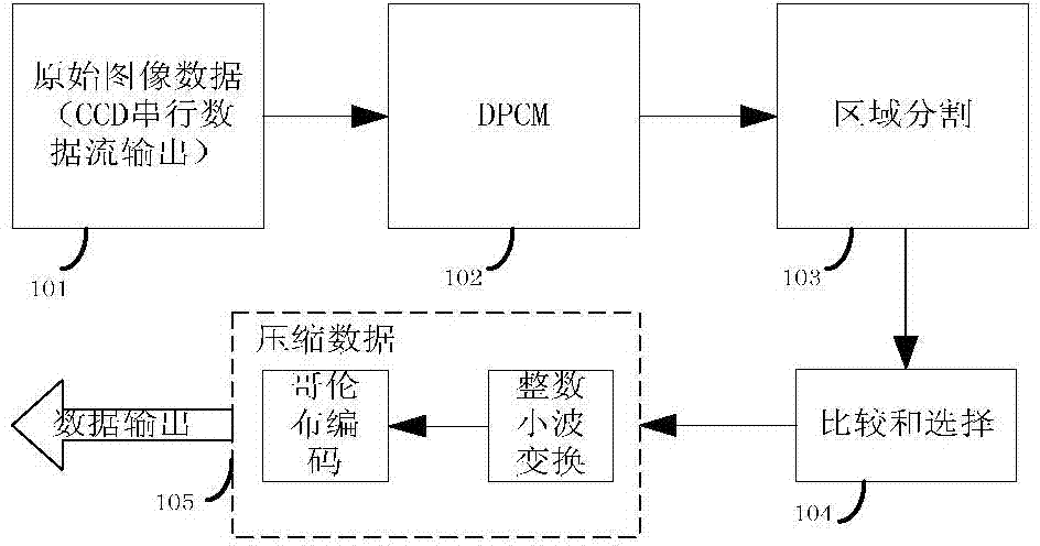
[0033] In the first step, this method first performs DCMP encoding on the collected raw data. Since industrial CT data has a better dynamic range and signal-to-noise ratio, DCMP encoding is more effective than the compression ratio obtained in other cases. First, the data matrix collected by one frame of the flat panel detector is divided into N small matrices of equal size. The value of N can be set according to the specific hardware parameters, and the prediction error values ​​inside the small matrix are added to obtain each small matrix. Forecast error and S n , the data average of each small matrix is Then the error rate is When the error rate P n When >i%, it indicates that the fluctuation of the data is large, and the differential encoding cannot achieve a good compression effect. Therefore, in order to improve the compression efficiency, the data matrix with an error rate greater than i% is compressed twice. Finally, a matrix with a size of N is added to indicate ...


PUM


Abstract

The invention relates to a CT (Computed Tomography) data compression mechanism. The data compression method comprises the following steps: acquiring original image data; caching the data acquired by a detector; differential encoding, namely, performing differential encoding for the cached data; area dividing, namely, dividing a data array into N small arrays with the same size; comparing and selecting, namely, comparing and screening separated data blocks with previous data blocks; data compression, namely, performing secondary compression for the part with large data difference. According to the CT data compression method, a nondestructive compression method for original industrial CT projection data is provided for mass industrial CT data acquiring and transmission; the data can be compressed in a CT device employing a high-resolution and large-area flat panel detector; therefore, the transmission efficiency and data compression ratio can be effectively raised.

Description

technical field [0001] The invention relates to a CT data compression method, in particular to a lossless compression method for industrial CT projection original data. Background technique [0002] Nowadays, with the rapid development of area array CCD detectors, CCDs with higher and higher resolutions and larger sizes have been applied to industrial CT products, and the resulting CT projection data has doubled, which gives Data storage and real-time transmission pose great difficulties. It limits or cannot meet the high precision and high resolution requirements of CT. [0003] Since industrial CT is used for inspection and flaw detection of industrial workpieces, it has special requirements for it, that is, the original data collected must have high fidelity requirements, and any degree of loss of image information is possible Will bring wrong inspection and flaw detection results. Based on the above considerations, the original data of CT projection adopts lossless en...

Claims


Application Information

Patent Timeline
IPC IPC(8): H04N19/63H04N19/13H04N19/85
Inventor 申济菘代志力陈研
Owner 重庆真测科技股份有限公司
Why Eureka
Try Eureka