Rolling rotor type compressor and air conditioner containing the same

A rolling rotor compressor technology, applied in the field of compressors, to achieve the effect of increasing the displacement, widening the displacement range, and improving the cooling and heating capacity

Active Publication Date: 2014-12-31
ZHUHAI GREE REFRIGERATION TECH CENT OF ENERGY SAVING & ENVIRONMENTAL PROTECTION
View PDF8 Cites 0 Cited by
  • Summary
  • Abstract
  • Description
  • Claims
  • Application Information

AI Technical Summary

Problems solved by technology

[0006] The purpose of the present invention is to provide a rolling rotor compressor and an air conditioner and heat pump water heater with it, so as to solve the problem of increasing the displacement of the compressor under a smaller cylinder diameter and widening the existing rolling rotor compressor. range of displacement

Method used


Image

  • Rolling rotor type compressor and air conditioner containing the same
  • Rolling rotor type compressor and air conditioner containing the same
  • Rolling rotor type compressor and air conditioner containing the same

Examples


Embodiment Construction

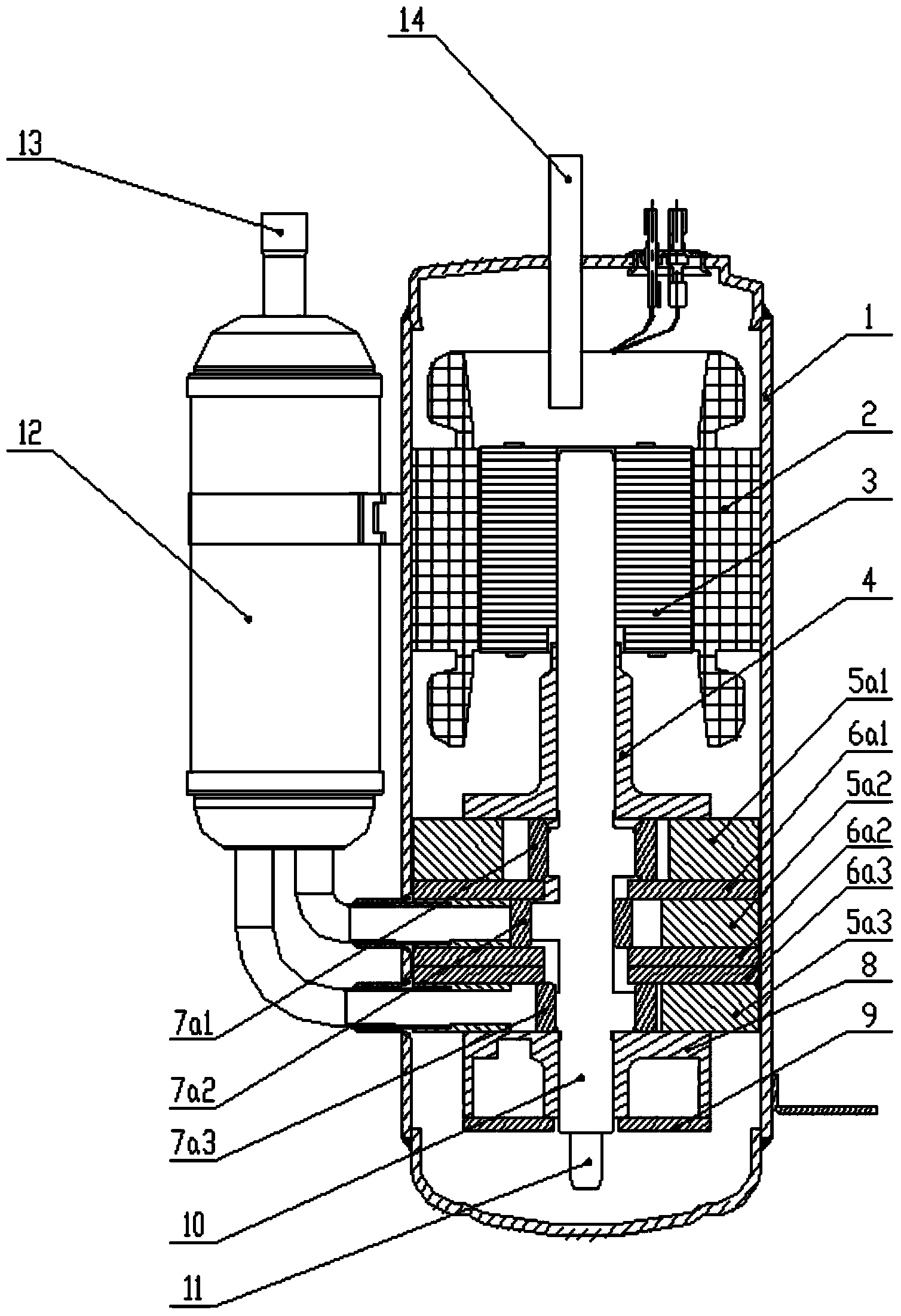
[0050] The compressor of the present invention will be described in detail below with reference to the drawings and embodiments.

[0051] In the description of the present invention, the orientation or positional relationship indicated by the terms "upper", "lower", "above", "below" etc. is based on the orientation or positional relationship shown in the drawings, and is only for the convenience of describing the present invention rather than Requirements that the invention must be constructed and operated in a particular orientation are not to be construed as limitations on the invention.

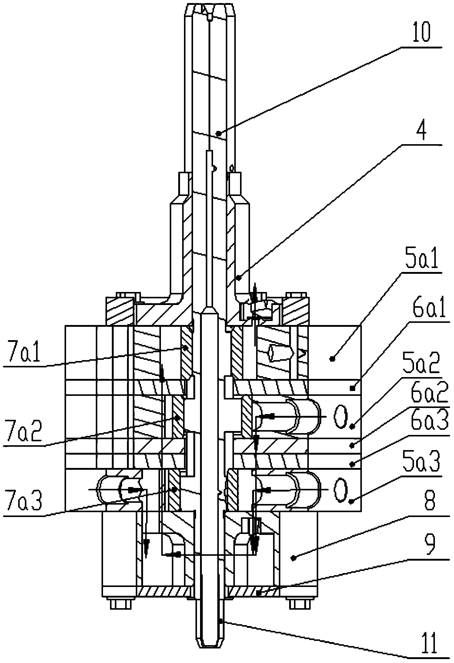
[0052] see figure 1Embodiment 1 of the rolling rotor compressor of the present invention includes: a casing 1, a motor assembly and a pump body assembly are arranged in the casing 1, the motor assembly includes a stator 2 and a rotor 3, and the crankshaft 10 is sleeved in the pump body assembly, The motor assembly drives the crankshaft 10 to rotate, thereby providing driving force for the...


PUM


Abstract

The invention provides a rolling rotor type compressor, including a shell and a low pressure compression part and a high pressure compression part arranged in the shell. The compressor is characterized in that the low compression part comprises at least two cylinders, and the high pressure compression part comprises one or more cylinders. The compressor also includes a flange assembly; the flange assembly includes an upper flange and a lower flange; the upper flange is cooperatively arranged with the high pressure compression part or the low pressure compression part; and when the upper flange cooperates with the high pressure compression part, the lower flange is cooperatively arranged with the low pressure compression part. The invention increases displacement of the rolling rotor type compressor without changing the diameter of the cylinder, broadens the displacement range of the rolling rotor type compressor under the existing cylinder diameter, and improves the cooling and heating capacity of the rolling rotor type compressor.

Description

technical field [0001] The invention relates to the field of compressors, in particular to a rolling rotor compressor and an air conditioner with the same. Background technique [0002] Existing rolling rotor type two-stage compressors are generally two-cylinder two-stage compressors. First, the displacement of the two-stage compressors is smaller than that of the two-cylinder single-stage compressors. Second, the balance of rotation is not as good as that of the two-cylinder single-stage compressors. However, there is a big gap between the energy efficiency and heating capacity of the single-stage compressor compared with the two-stage compressor, and the displacement of the two-cylinder two-stage compressor is enlarged. [0003] The existing two-stage rolling rotor compressor is generally two-cylinder two-stage, and the displacement of the two-stage compressor is much smaller than that of the two-cylinder compressor. Now, the compressor displacement is generally increased ...

Claims


Application Information

Patent Timeline
Patent Type & Authority Applications(China)
IPC IPC(8): F04C23/00
Inventor 巫华龙黄辉胡余生魏会军杨欧翔王相
Owner ZHUHAI GREE REFRIGERATION TECH CENT OF ENERGY SAVING & ENVIRONMENTAL PROTECTION
Why Eureka
Try Eureka