Axial turbomachine compressor drum with dual means of blade fixing

A technology for axial flow turbines and low-pressure compressors, applied in the direction of blade support components, machines/engines, mechanical equipment, etc., can solve problems such as expensive machining, bulky and complex structures, and achieve the effect of surface simplification

Active Publication Date: 2014-12-31
SAFRAN AERO BOOSTERS SA
View PDF9 Cites 2 Cited by
  • Summary
  • Abstract
  • Description
  • Claims
  • Application Information

AI Technical Summary

Problems solved by technology

In addition, its implementation requires complex and expensive machining
In addition, its structure is bulky and bulky

Method used


Image

  • Axial turbomachine compressor drum with dual means of blade fixing
  • Axial turbomachine compressor drum with dual means of blade fixing
  • Axial turbomachine compressor drum with dual means of blade fixing

Examples


Embodiment Construction

[0037] In the following description, the terms inner or outer refer to a position relative to the axis of rotation of the axial turbine.

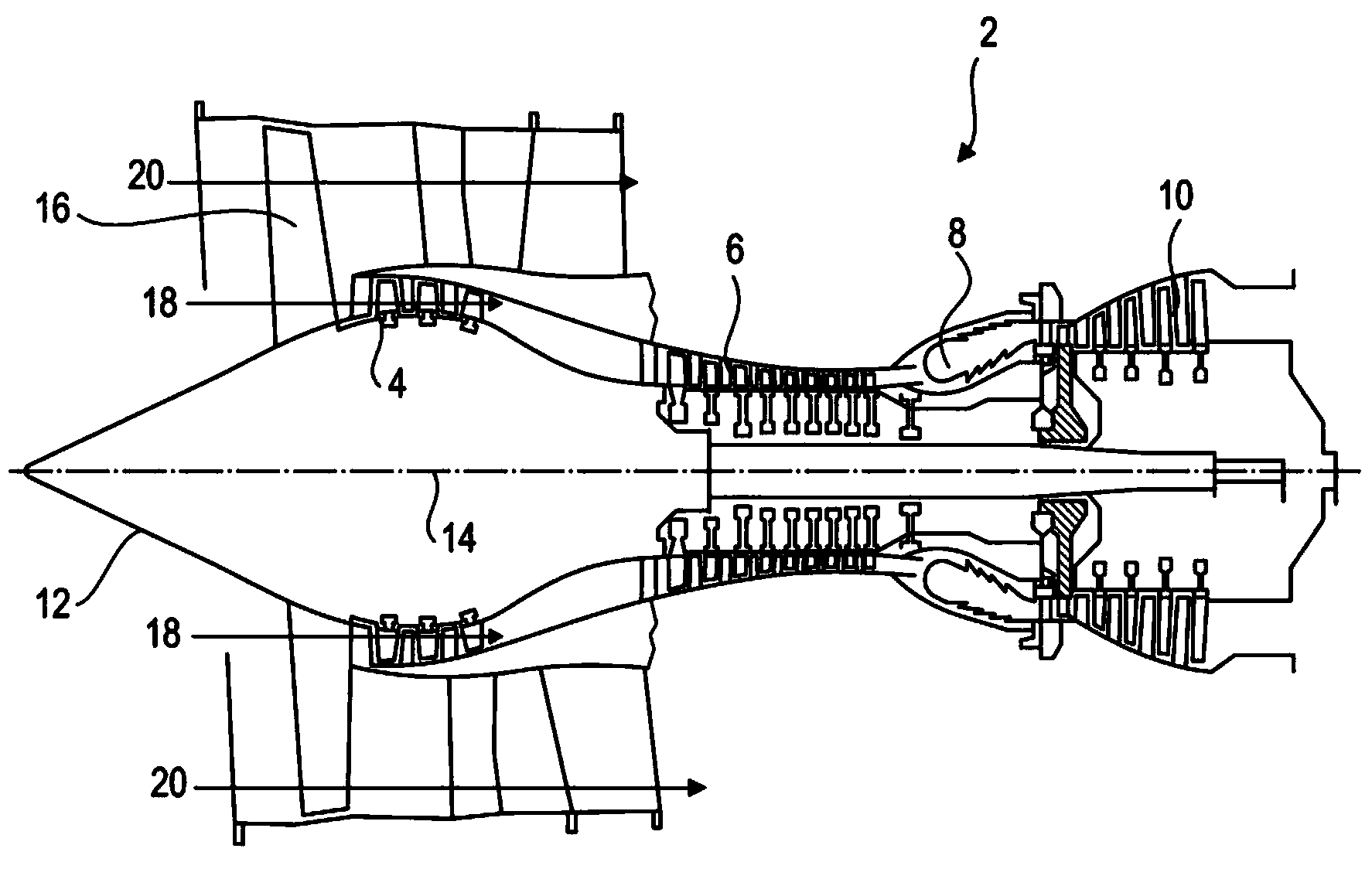
[0038] figure 1 A schematic representation of an axial turbine. In this case, it is a double-flow turbojet. The turbojet engine 2 comprises a first compression stage, a so-called low-pressure compressor 4 ; a second compression stage, a so-called high-pressure compressor 6 ; a combustion chamber 8 ; and one or more turbine stages 10 . In operation, the mechanical power of the turbine 10 is transmitted via the central shaft to the rotor 12 and drives the two compressors 4 and 6 . The speed change mechanism increases the rotational speed delivered to the compressor. Alternatively, different turbine stages can each be coupled to a compressor stage via respective concentric shafts. A compressor stage includes several rows of rotor blades associated with rows of stator blades. The rotation of the rotor about its axis of rotation 14 generate...


PUM


Abstract

The present application relates to a rotor drum 40 of a low-pressure compressor of an axial turbomachine. The drum 40 includes a wall 42 generally symmetrical in revolution about an axis 14 and following a generally curved profile. The wall 42 is configured to support a plurality of blade rows 24, 26, 28. A first blade row 24 is formed by an annular platform 46 integrally formed with the wall 42 at the peak of its profile in relation to the axis 14; and a second blade row 26 directly downstream of the first 24; and a third blade row 28 directly upstream of the first 24; are formed by one or more blade-retaining grooves 54 formed on the wall. The first blade row 24 and the drum form an integral assembly, eliminating certain vibrations. Anchoring the blades is hybrid or mixed. The rotor may be mounted in a housing with ring-shaped stators.

Description

technical field [0001] The invention relates to a rotor of an axial turbine. More specifically, the present invention relates to a rotor drum of an axial turbomachine compressor. The invention relates to an axial flow turbine fitted with a low pressure compressor rotor drum. Background technique [0002] Turbines enable gases to be compressed, burned, and expanded. In this way the turbine provides mechanical energy. To perform these steps, a turbomachine includes a turbine and a compressor fitted with a rotor and housing. [0003] The inner surface of the housing and the outer surface of the rotor define the outline of the main flow path. It has variations in its annular cross-section. Its inner and outer profiles can increase and decrease in diameter along the axis of the engine. In compressors, especially low-pressure compressors, the outer casing usually has a diameter that decreases downstream. From upstream to downstream, the diameter of the rotor may increase an...

Claims


Application Information

Patent Timeline
Patent Type & Authority Applications(China)
IPC IPC(8): F04D29/32F04D29/34
CPCF04D29/322F04D29/023F01D5/06F01D5/063F01D5/3007F01D11/001
Inventor E.佩纳尔弗卡斯特罗
Owner SAFRAN AERO BOOSTERS SA
Why Eureka
Try Eureka