Light guide plate and backlight module using same

A technology of backlight module and light guide plate, which is applied in the field of optical components, can solve the problems of limited freedom of mold design, etc., and achieve the effects of improving light leakage and dark areas, good light utilization efficiency, and good uniformity

Inactive Publication Date: 2017-04-12
YOUNG LIGHTING TECHNOLOGY INC
View PDF7 Cites 0 Cited by
  • Summary
  • Abstract
  • Description
  • Claims
  • Application Information

AI Technical Summary

Problems solved by technology

In this way, the freedom of mold design will be limited

Method used


Image

  • Light guide plate and backlight module using same
  • Light guide plate and backlight module using same
  • Light guide plate and backlight module using same

Examples


Embodiment Construction

[0036] The aforementioned and other technical contents, features and effects of the present invention will be clearly presented in the following detailed description of a preferred embodiment with accompanying drawings. The directional terms mentioned in the following embodiments, such as: up, down, left, right, front or back, etc., are only the directions of the drawings. Accordingly, the directional terms are used to illustrate and not to limit the invention.

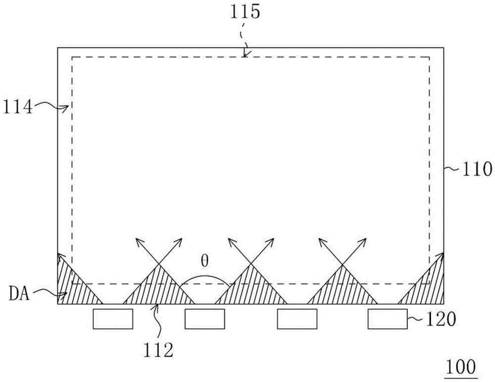
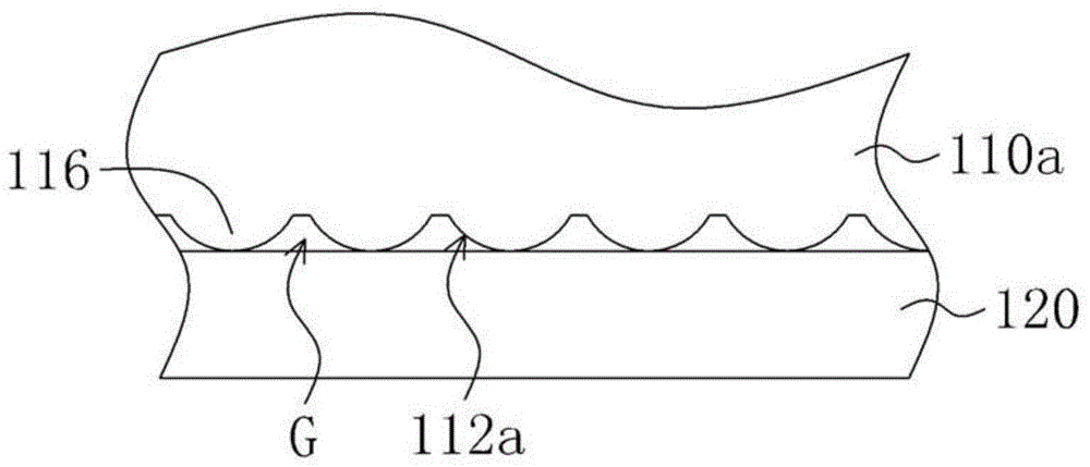
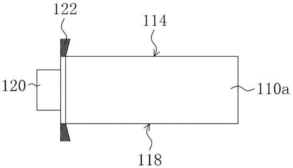
[0037] Figure 4 It is a schematic top view of a backlight module according to an embodiment of the present invention, Figure 5 is along Figure 4 A schematic cross-sectional view of the A-A line, and Figure 6A yes Figure 4 A schematic perspective view of the contour lines of the single first depression structure in Figure 6B yes Figure 4 Schematic diagram of the top view of the contour line of the single first depression structure in Figure 7A , Figure 7B and Figure 7C are along Figure 4 The cross-...


PUM

PropertyMeasurementUnit
angleaaaaaaaaaa

Abstract

A light guide plate possesses a light incident surface, a first surface, a second surface and a plurality of first recess structures relative to the light incident surface. The first surface is connected with the light incident surface and the second surface, and each recess structure extends from the light incident surface to the second surface, is arranged on the first surface, and possesses an opening exposed on the first surface. Each opening is widened gradually from the light incident surface to the second surface and in the width vertical with a first direction and parallel with a second direction of the first surface. The present invention also provides a backlight module using the light guide plate.

Description

technical field [0001] The present invention relates to an optical element, and in particular to a light guide plate and a backlight module using the same. Background technique [0002] figure 1 It is a schematic top view of a conventional backlight module. Please refer to figure 1 A conventional backlight module 100 includes a light guide plate 110 and a plurality of light emitting diodes 120 , wherein the light emitting diodes 120 are disposed beside the light incident surface 112 of the light guide plate 110 . The light beam provided by the LED 120 enters the light guide plate 110 through the light incident surface 112 , and the light guide plate 110 is used for converting the light beam into a surface light source emitted from the light exit surface 114 thereof. The light-emitting surface 114 has an active area 115 , where the active area 115 refers to a portion of the light-emitting surface 114 corresponding to the display area of ​​the display panel. In other words...

Claims


Application Information

Patent Timeline
Patent Type & Authority Patents(China)
IPC IPC(8): G02F1/13357G02B6/00
Inventor 胡佳状
Owner YOUNG LIGHTING TECHNOLOGY INC
Why Eureka
Try Eureka