
Two-wire test probe device and application method thereof

A test probe and second-line technology, which is applied in the field of printed circuit board testing devices, can solve problems such as printed circuit board scrapping, dents, and scratches on printed circuit boards, and achieve the effect of saving manpower

Active Publication Date: 2017-06-30
HANS CNC SCI & TECH
View PDF10 Cites 0 Cited by
  • Summary
  • Abstract
  • Description
  • Claims
  • Application Information

AI Technical Summary

Problems solved by technology

However, due to the fast movement speed, it is difficult to control the pressure exerted by the test probe device on the printed circuit board. After the test probe contacts the printed circuit board, the contact force is too large, resulting in scratches or dents on the printed circuit board, resulting in printed circuit board Circuit board scrap

Method used


Image

  • Two-wire test probe device and application method thereof
  • Two-wire test probe device and application method thereof
  • Two-wire test probe device and application method thereof

Examples


Embodiment Construction

[0032] In order to facilitate the understanding of the present invention, the present invention will be described more fully below with reference to the associated drawings. Preferred embodiments of the invention are shown in the accompanying drawings. However, the present invention can be embodied in many different forms and is not limited to the embodiments described herein. On the contrary, the purpose of providing these embodiments is to make the disclosure of the present invention more thorough and comprehensive.

[0033] It should be noted that when an element is referred to as being “fixed” to another element, it can be directly on the other element or there can also be an intervening element. When an element is referred to as being "connected to" another element, it can be directly connected to the other element or intervening elements may also be present. The terms "vertical," "horizontal," "left," "right," and similar expressions are used herein for purposes of ill...


PUM


Abstract

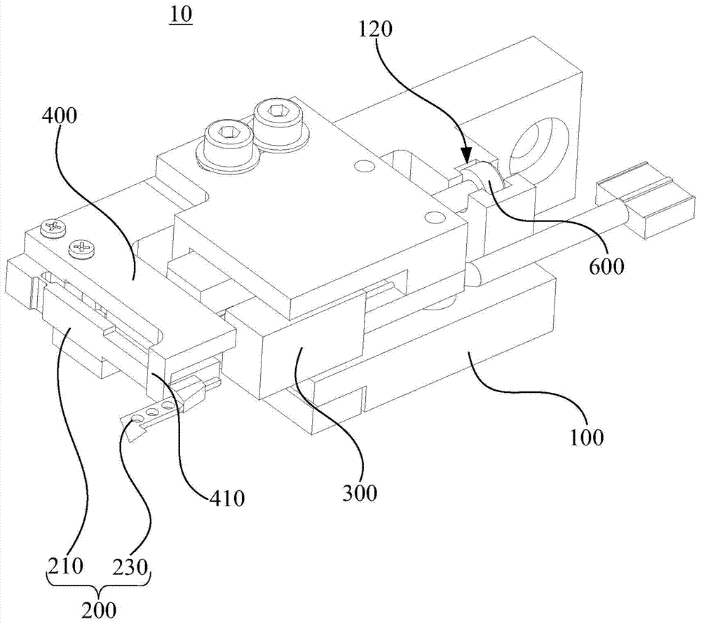
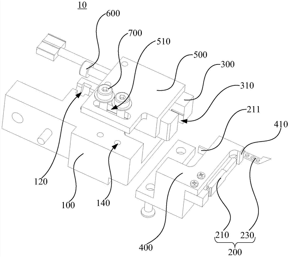
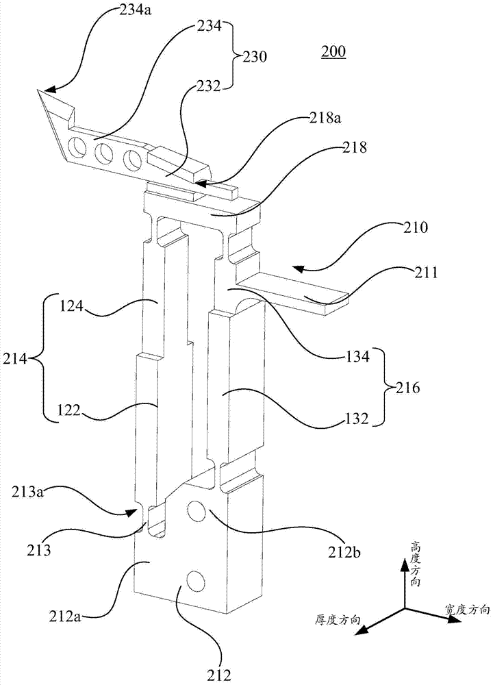
The invention relates to a two-wire testing probe device. The two-wire testing probe device comprises a traction mechanism, a main body fixing seat, a testing probe and a photoelectric sensor, wherein the main body fixing seat can move under the drive of the traction mechanism; the testing probe comprises an elastic support and a probe which is arranged on the elastic support, and a protruding light shielding block is arranged on the elastic support; one side, close to the testing probe, of the photoelectric sensor is provided with a notch, and the photoelectric sensor can produce counter-emitted light which is emitted from one side of the notch to the other side of the notch; the light shielding block can stretch into the notch and shield the counter-emitted light, the elastic support is deformed during testing to change light amount of the shielded counter-emitted light, changing output voltage is produced by the photoelectric sensor and the traction mechanism controls the pressure applied by the testing probe to a printed circuit board according to the value of output voltage. The two-wire testing probe device can effectively control the contact force between the testing probe and the printed circuit board. The invention further provides a two-wire testing probe device application method.

Description

technical field [0001] The invention relates to a printed circuit board (PCB) test device, in particular to a two-wire test probe device and an application method thereof. Background technique [0002] The probe testing device is generally used for testing a printed circuit board (PCB). During testing, a test probe needs to be in contact with the circuit board. According to different test methods, there are two kinds of test probe devices, two-wire and four-wire. The two-wire test probe device is used for occasions where the accuracy of the resistance value is not high, while the four-wire test probe device is used for the low-resistance test occasions where the resistance value is required to be high. [0003] During the test of the traditional two-line test probe device, the probe usually lowers and lifts the needle at a speed of 10 to 50 times per second to contact different test points. For reliable testing, the probes need to be securely attached to the test board. A...

Claims


Application Information

Patent Timeline
Patent Type & Authority Patents(China)
IPC IPC(8): G01R1/067G01R31/00
Inventor 谭艳萍黄俊华陈百强王星翟学涛杨朝辉高云峰
Owner HANS CNC SCI & TECH
Learn More