

Solar LED street lamp with dust removal function and dust removal method thereof
A technology for LED street lamps and LED lamps, which is applied in directions such as in-machine power supply, cleaning methods and utensils, chemical instruments and methods, etc., can solve the problems of reducing the practicability of solar street lamps, affecting the lighting work of LED lamps, and increasing dust coverage, etc. Improve lighting work, improve practicality, increase the effect of cleanliness
- Summary
- Abstract
- Description
- Claims
- Application Information
AI Technical Summary
Problems solved by technology
Method used
Image

Examples
Embodiment Construction
[0029] The following will clearly and completely describe the technical solutions in the embodiments of the present invention with reference to the accompanying drawings in the embodiments of the present invention. Obviously, the described embodiments are only some, not all, embodiments of the present invention.
[0030] Examples of the described embodiments are shown in the drawings, wherein like or similar reference numerals designate like or similar elements or elements having the same or similar functions throughout. The embodiments described below by referring to the figures are exemplary and are intended to explain the present invention and should not be construed as limiting the present invention.
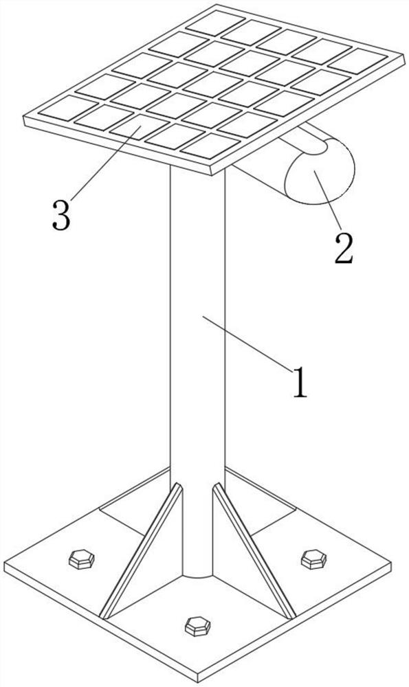
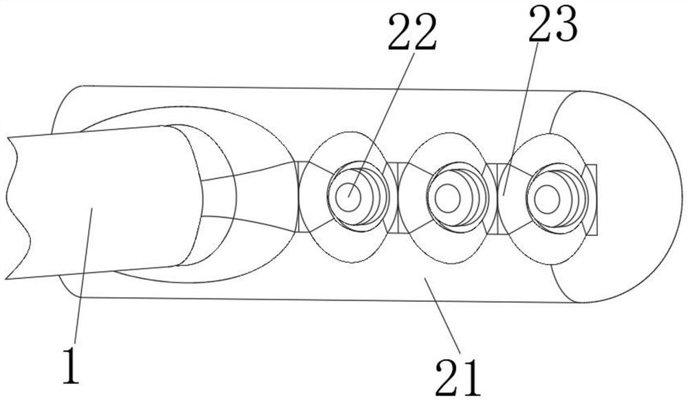
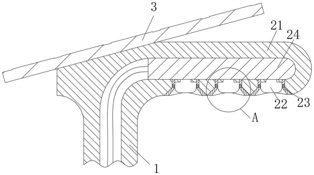
[0031] see Figure 1-5 , the present invention provides a technical solution: a solar LED street lamp with a dust removal function, including a street lamp bracket 1, an LED lamp and a cleaning mechanism 2 are fixedly connected to the top of the street lamp bracket 1, and th...
PUM
 Abstract
Description
Claims
Application Information