Carrying device and carrying platform flatness adjusting method

A technology of a bearing device and an adjustment method, applied in nonlinear optics, instruments, optics, etc., can solve the problems of uneven and stable blowing effect of the air outlet unit, large adjustment error, correction error, etc., to improve the sagging deformation phenomenon, accurate The effect of flatness correction and avoiding false detection

Inactive Publication Date: 2014-12-31
AU OPTRONICS CORP
View PDF0 Cites 3 Cited by
  • Summary
  • Abstract
  • Description
  • Claims
  • Application Information

AI Technical Summary

Problems solved by technology

[0003] As mentioned above, although it improves the flatness of the bearing surface 11 of the carrier 10 to a certain extent, it also has certain defects: First, the above-mentioned structure is easy to cause the air outlet unit to be damaged due to the instability of the air pressure source. The air blowing effect is not uniform and stable, resulting in correction errors; secondly, when the carrier 10 is rotated to a position other than the corresponding position of the above-mentioned solid line or dotted line, the air outlet unit cannot realize the blowing correction of the carrier 10; in addition, due to the above-mentioned The solution uses air blowing to improve the flatness of the stage 10, so to a certain extent, it is impossible to adjust the air blowing effect in detail, that is, the adjustment error will be relatively large

Method used


Image

  • Carrying device and carrying platform flatness adjusting method
  • Carrying device and carrying platform flatness adjusting method
  • Carrying device and carrying platform flatness adjusting method

Examples


Embodiment Construction

[0029] In order to have a further understanding of the purpose, structure, features, and functions of the present invention, the following detailed descriptions are provided in conjunction with the embodiments.

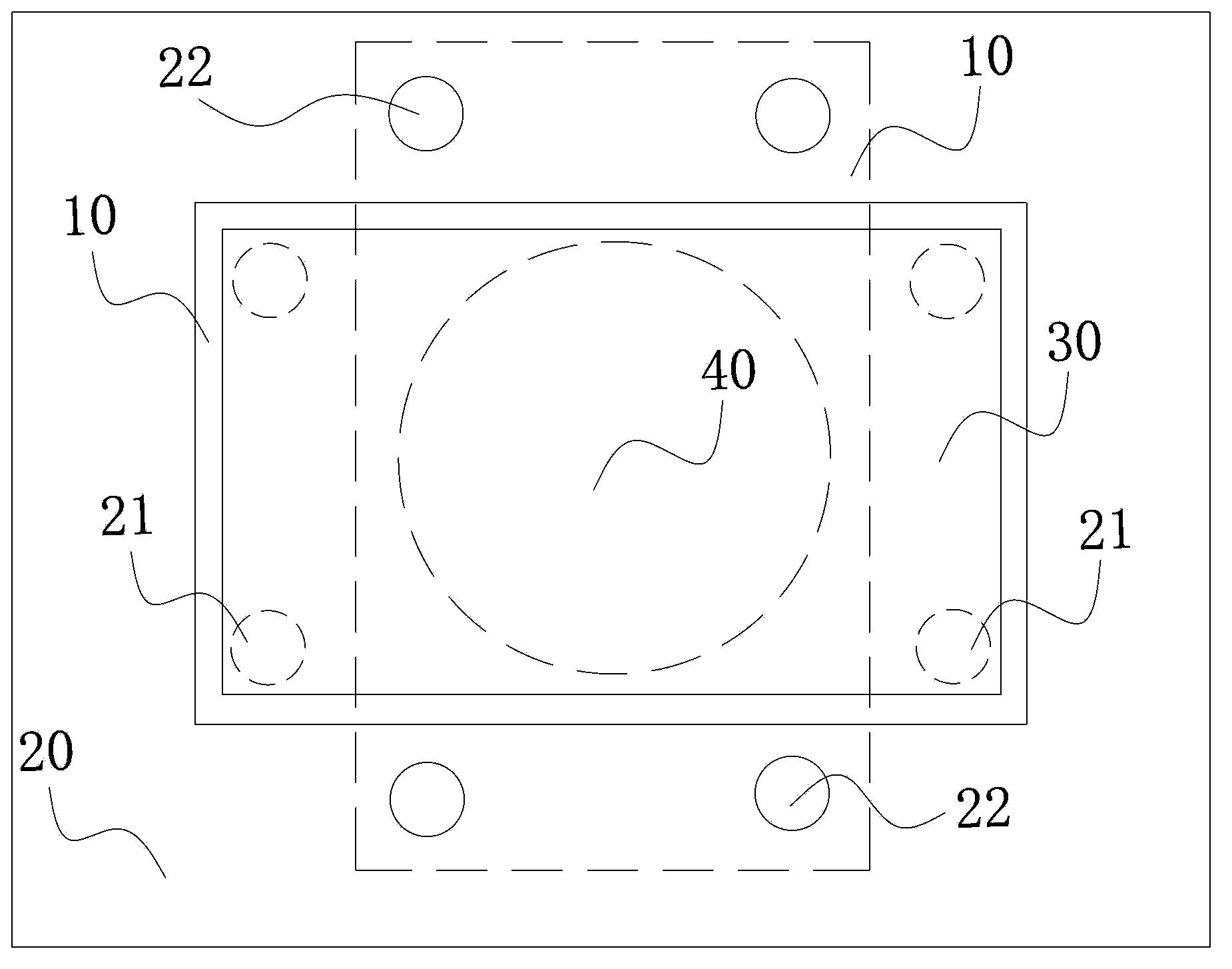
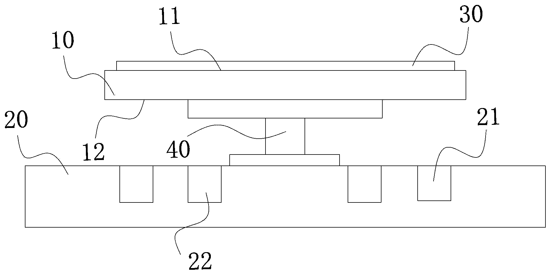
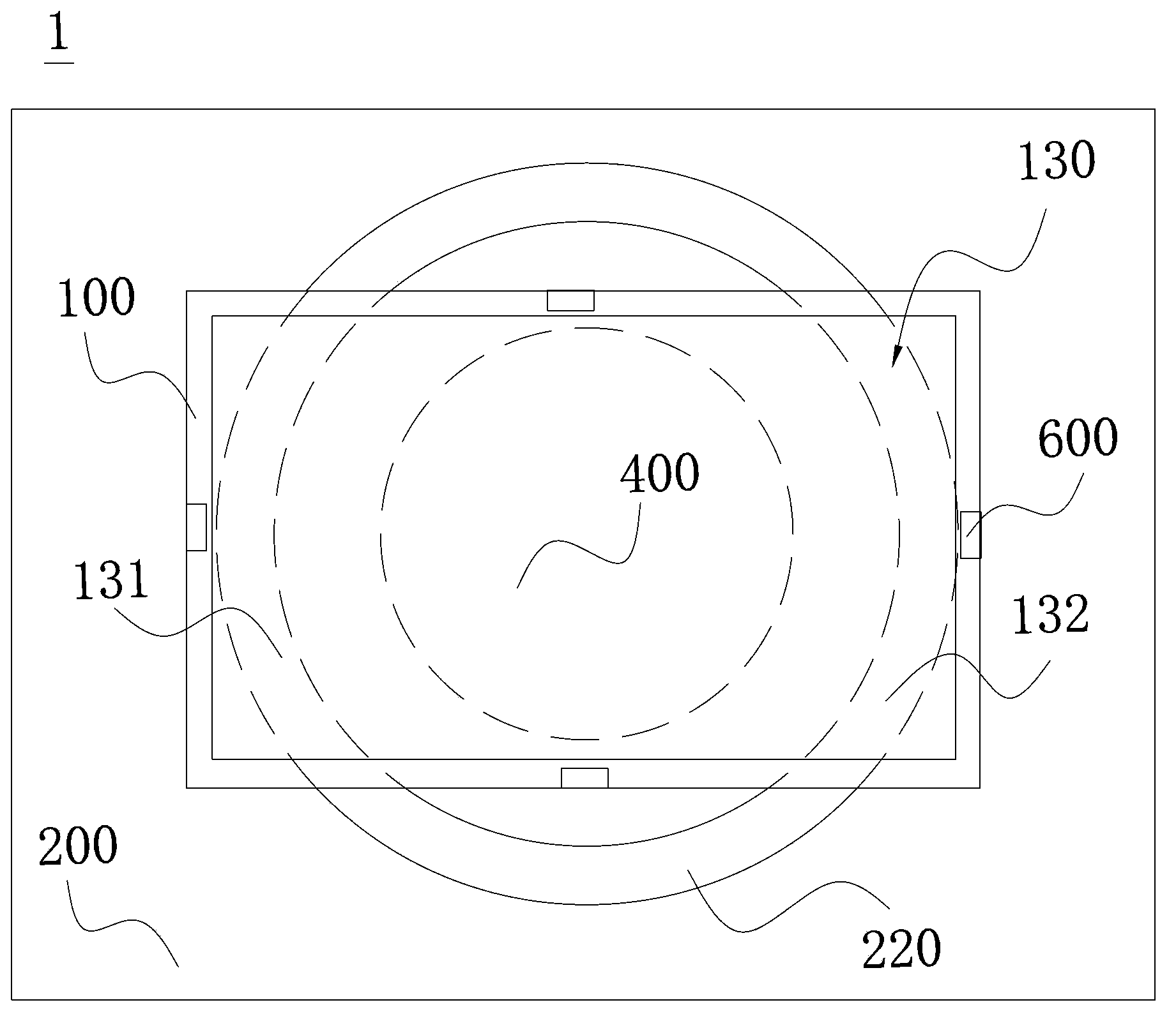
[0030] Please refer to Figure 2A , 2B , are schematic top and side views of the carrier device in the first state, respectively, in an embodiment of the present invention. The carrying device 1 of the present invention is mainly used for carrying the substrate 300, and the substrate can be a liquid crystal display panel or a touch panel, but not limited thereto, and it can also be other boards to be tested. Wherein, the carrying device 1 includes a stage 100 , a base 200 , a driving part 400 , at least one set of electromagnet modules 500 and at least one sensing module 600 . Wherein, in this embodiment, the carrying device 1 has a set of electromagnet modules 500 and four sensing modules 600 as an example for illustration. The stage 100 is arranged on the base 20...


PUM


Abstract

The invention provides a carrying device, which is used for carrying a substrate. The carrying device comprises a carrying platform, a base, electromagnet modules, sensing modules and a logic control part, wherein each electromagnet module comprises a first electromagnet group and a second electromagnet group which are oppositely arranged, repulsive force is formed when the two electromagnet groups are electrified; the sensing modules are used for detecting actual vertical distance between first positions, corresponding to the sensing modules on a second surface and a third surface; the logic control part is used for receiving the actual vertical distance detected by the sensing modules, comparing the actual vertical distance with a preset value and controlling the repulsive force of the corresponding electromagnet modules according to comparison results to adjust the actual vertical distance to be equal to the preset value. By using the carrying device, the phenomenon of downward sagging deformation at the edges or corners of the carrying platform can be effectively improved, flatness correction can be more accurately conducted to upper and downward sagging deformation positions of the carrying platform, and the detection mistake of detection equipment in the prior art is avoided.

Description

technical field [0001] The invention relates to a bearing device, in particular to a bearing device capable of real-time self-adaptive adjustment of the flatness of a carrier platform and an adjustment method thereof. Background technique [0002] At present, in the existing liquid crystal panel production process, especially in the production process of the front-end substrate, it is often necessary to detect various electrical or physical defects on the substrate, so a load-carrying device, to carry the substrate for the detection equipment to perform bad detection on it, such as Figure 1A , 1B As shown in FIG. 2 , they are schematic top and side views of the carrying device in the prior art, respectively. The carrying device in the prior art mainly includes a stage 10, a base 20 and a driving part 40. The stage 10 is arranged on the base 20 for carrying the substrate 30, and the driving part 40 is fixed on the base 20. The carrier 10 is also connected to drive the carr...

Claims


Application Information

Patent Timeline
Patent Type & Authority Applications(China)
IPC IPC(8): G02F1/13
Inventor 江志民
Owner AU OPTRONICS CORP
Why Eureka
Try Eureka