Information display body and connecting part used for the information display body

A technology for information display and connection components, applied in display devices, applications, clothing, etc., can solve the problems of easy falling off, falling off, and the installation mechanism of information display cards is not effective, and achieves the effect of high availability

Active Publication Date: 2018-05-01
科林株式会社
View PDF7 Cites 0 Cited by
  • Summary
  • Abstract
  • Description
  • Claims
  • Application Information

AI Technical Summary

Problems solved by technology

[0007] However, the name tag with a clip disclosed in Patent Document 1 uses a clip to clip the clothes and wear it, so there is no need to make holes in the clothes, but there is a problem that it is easy to fall off depending on the material of the clothes, and the name tag used in schools The users of the name tags are lively children, so they can't stand their intense sports and fall off
[0008] On the other hand, in the method disclosed in the above-mentioned patent document 2, there is a problem that the clothing needs to be processed in advance so that the locking part holding the pin shaft part can be attached to the clothing. Clothes that are frequently worn like this are effective as an installation mechanism for information display boards, but such as information display boards distributed in meetings or parties, etc., are not suitable as an installation mechanism for information display boards that are only used on that occasion. not valid

Method used


Image

  • Information display body and connecting part used for the information display body
  • Information display body and connecting part used for the information display body
  • Information display body and connecting part used for the information display body

Examples


Embodiment approach 1

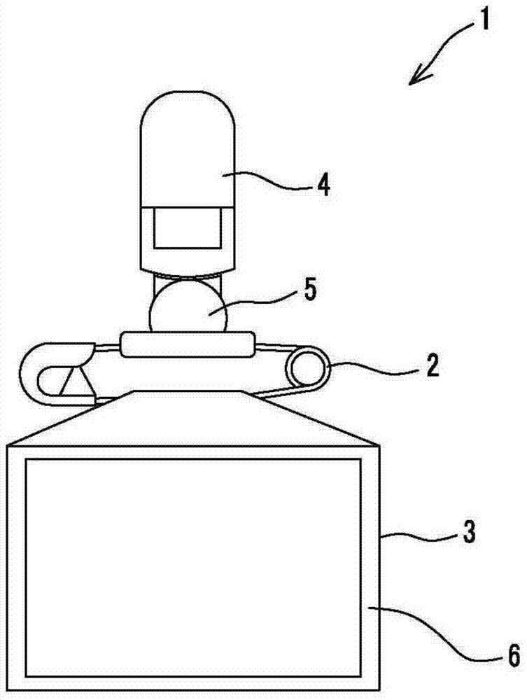
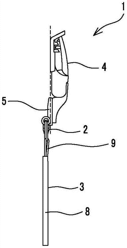
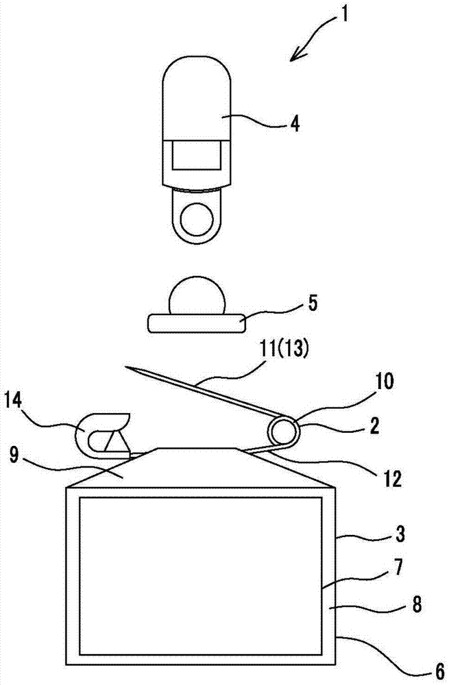
[0043] Such as Figure 1 ~ Figure 3 As shown, the information display body 1 involved in this embodiment is composed of the following parts: an information display part 3, equipped with a first wearing part 2 for pin-fixing on clothes or other worn objects; a second wearing part 4, for Clamping the object to be worn; and the connecting part 5 interposed between the first wearing part 2 and the second wearing part 4 to connect the first wearing part 2 and the second wearing part 4 .

[0044] Such as image 3 As shown, the information display part 3 is composed of the following parts: an information display part 6 for displaying information such as name or serial number; and a first wearing part 2 for fixing the information display part 6 to the object to be worn.

[0045] The information display unit 6 is composed of a card 7 on which information is displayed and a sleeve 8 capable of accommodating the card 7 . In addition, the cover portion 8 is formed into a pocket shape by...

Embodiment approach 2

[0062] This embodiment is a modified example of the two fitting parts in the first embodiment. Figure 19 in, with Figure 1 to Figure 18 The same symbols indicate the same or corresponding parts.

[0063] Such as Figure 19 As shown, the first fitting portion 39 according to the present embodiment protrudes from the surface of the holding portion 18 of the one side holding body 15 of the second wearing member 4 and extends parallel to the rotation direction of the operating body 17 . Furthermore, the second fitting portion 40 according to the present embodiment is formed by cutting the back surface of the disc portion 35 of the connection member 5 into a concave shape. Furthermore, the second wearing member 4 is detachably and rotatably connected by fitting the second fitting portion 40 into the first fitting portion 39 of the connecting member 5 .

Embodiment approach 3

[0065] This embodiment is a modified example of the second wearing part in the first embodiment, and Figure 20 and Figure 21 in, with Figure 1 to Figure 18 The same symbols indicate the same or corresponding parts.

[0066] The second wearing member 41 according to the present embodiment has a form in which the cylindrical portion 34 of the connecting member 5 is integrally formed with the operation body 17 of the second wearing member 4 in the first embodiment. Specifically, as Figure 20 and Figure 21 As shown, a cylindrical portion 42 through which the needle 13 of the first wearing member 2 can be inserted and extracted is integrally formed at the front end of the operating body 17 . In addition, the cylindrical portion 42 is formed to pass through in a direction perpendicular to the rotation direction of the operation body 17 and the opening direction of the pair of clamping portions 18 , 23 .


PUM


Abstract

The present invention provides an information display board which can select a wearing mechanism for the clothes according to conditions, and does not influence another one wearing mechanism on the condition of using the wearing mechanism. In the information display body of the present invention, a second wearing member is detachably connected on a first wearing member arranged on an information display part via the connecting part, wherein the first wearing member is equipped with a needle fixed on the worn object, and the second wearing member is equipped with a pair of clamping parts and an operating part. The pair of clamping parts is used to clamp the worn object, and the operating part extends towards the direction reverse with the opening directions of the pair of clamping parts in the state that the pair of clamping parts is clamped. The second wearing member is configured to rotate the operating part to thereby open and close the pair of clamping parts, the first wearing member is connected with the connecting part by plugging the needle in or out a cylinder, and under the state that the rotation direction of the operating part faces the direction vertical and intersected with the penetration direction of the cylinder, the second wearing member is connected with the connecting part.

Description

technical field [0001] The present invention relates to an information display body and a connecting member used for the information display body. Background technique [0002] As we all know, most of the information display cards such as name tags used in schools or identification tags distributed in meetings or assemblies are in the form of pins. The hole through which the needle of the pin passes, which makes most users stay away. [0003] Therefore, many information display cards that can be worn without opening holes in clothes have been developed. For example, in the following patent document 1, a name tag with a clip is disclosed, that is, two clips that are fixed at one end and opened and closed at the other end. The fixed end of the sheet fixes the handle plate of the clip, and snap-on snap-on tools that engage with each other are provided at each open-close end so that the same open-close ends are combined together, and the above-mentioned snap-on clips between th...

Claims


Application Information

Patent Timeline
Patent Type & Authority Patents(China)
IPC IPC(8): G09F7/18
CPCA44B9/12G09F1/10G09F3/16G09F3/18
Inventor 高林正喜
Owner 科林株式会社
Why Eureka
Try Eureka