
socket electrical connection structure

A technology of electrical connection and socket, applied in the direction of contact parts, etc., can solve the problem of not being able to have convenient connection at the same time, and achieve the effects of convenient production, good versatility and convenient connection

Active Publication Date: 2016-06-15
BULL GRP CO LTD
View PDF5 Cites 0 Cited by
  • Summary
  • Abstract
  • Description
  • Claims
  • Application Information

AI Technical Summary

Problems solved by technology

[0005] The invention provides a socket electrical connection structure that is convenient to connect and manufacture, and solves the problem that the existing socket module connection method cannot combine the advantages of convenient connection, convenient manufacture and convenient socket modular production

Method used


Image

  • socket electrical connection structure
  • socket electrical connection structure
  • socket electrical connection structure

Examples


Embodiment 1

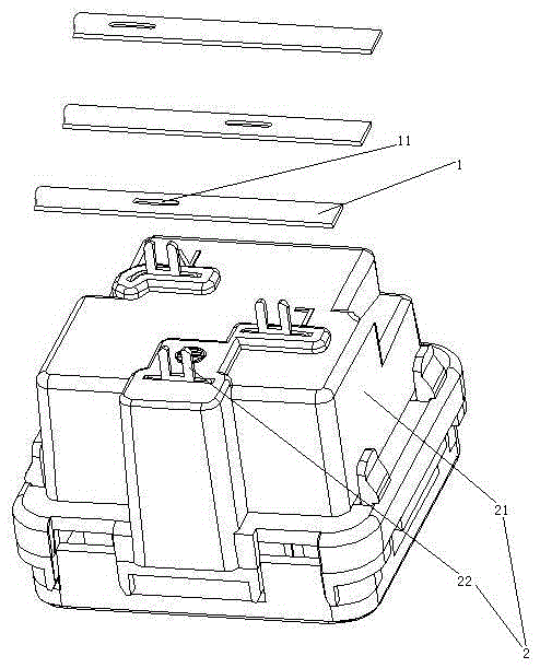
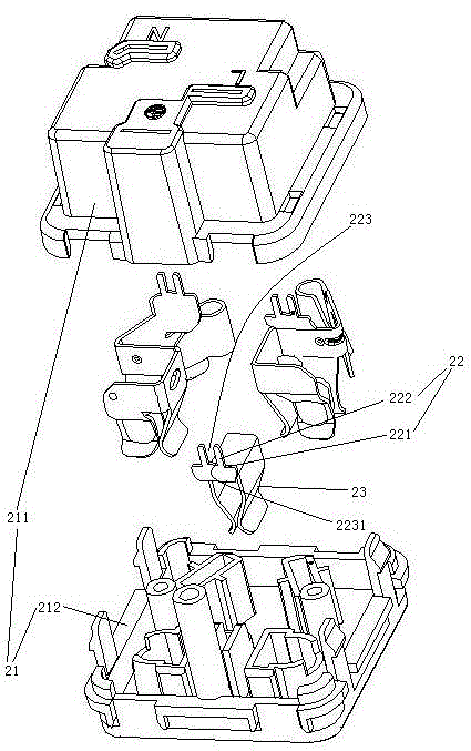
[0026] Embodiment one, see figure 1 , a socket electrical connection structure, comprising a conductive strip 1 and a socket module 2 . The socket module 2 includes an insulating shell 21 and a connector 22 passing through the shell. There are three connectors 22. The three connectors 22 are L-pole connectors, N-pole connectors and E-pole connectors respectively (some two-pole socket modules are not provided with E-pole connectors).

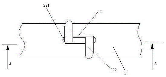
[0027] The conductive strip 1 is a flat structure. The width direction of the conductive strip 1 is parallel to the plane where the bottom surface of the casing 21 is located. The conductive strip 1 is a copper strip. There are three conductive strips 1. The three conductive strips 1 are L pole conductive strips, N pole conductive strips and E pole conductive strips respectively. The conductive strip 1 is provided with a connecting through hole 11 . The connection via hole 11 penetrates the conductive strip 1 along the thickness direction ...

Embodiment 2

[0034] Embodiment two, see Figure 5 , the difference from the first embodiment is that a solder joint 4 is provided between the connecting head 22 and the connecting through hole 11 . The solder joint 4 connects the connection head 22 and the busbar 1 together. The solder joint 4 is located between the two pins 222 .

Embodiment 3

[0035] Embodiment three, see Figure 6 , the difference from Embodiment 1 is that the two prongs 22 are bent in the same direction.


PUM


Abstract

The invention relates to an electrical connecting structure of a socket. The electrical connecting structure of the socket comprises a socket module and a bus bar, wherein the socket module comprises an insulated enclosure and a plug bush which is located in the enclosure and is used for being connected with a plug, a connecting through hole is formed in the bus bar, a connector which penetrates out of the enclosure is arranged on the plug sleeve, the connector comprises a supporting step which exceeds the outer surface of the enclosure and two pins which are arranged on the supporting step, the bus bar is placed on the supporting step, and the pins penetrate through the connecting through hole and are hooked onto the bus bar. The electrical connecting structure of the socket provided by the invention is convenient to connect and manufacture, and solves the problem that the existing socket module and power supply connecting method cannot simultaneously have the advantages of convenience in connection, convenience in manufacturing and convenience in socket modularized production.

Description

technical field [0001] The invention relates to a socket, in particular to a socket electrical connection structure. Background technique [0002] The socket includes a socket shell, a conductive strip arranged in the socket shell and a socket for connecting with a plug. When in use, the power supply passes through the power cord, the conductive strip and the electrical connection structure, so that the socket is charged, and the pin of the plug is inserted into the socket to obtain electricity. In order to facilitate the modular production of the socket, the socket in the socket is made as a socket module and installed in the socket shell. The sockets are installed in an insulating shell, and the sockets of the same polarity are connected to the power supply through the same electrical connection structure. There are two ways for the existing socket module to connect to the power supply: one is to set the socket in the socket module with lead-out pins, and the lead-out pi...

Claims


Application Information

Patent Timeline
Patent Type & Authority Patents(China)
IPC IPC(8): H01R13/10
Inventor 章卫军诸葛继亮
Owner BULL GRP CO LTD
Learn More