
Connecting structure of steel frame light roof panel and H-shaped steel beam

A technology for connecting structures and roof panels, applied in the direction of floors, building components, building structures, etc., can solve the problems of complex stress on roof panels and steel beams, weakening the strength of drilled sections, and failure of roof panel welding, so as to adapt to the main structure. Deformation, saving installation time, simple effect of on-site assembly

Pending Publication Date: 2021-10-29
SHENYANG JIANZHU UNIVERSITY
View PDF0 Cites 0 Cited by
  • Summary
  • Abstract
  • Description
  • Claims
  • Application Information

AI Technical Summary

Problems solved by technology

Therefore, cracks often appear at the welding seam, and the steel girder's bearing capacity is reduced or deformed due to welding stress. The roof panel cannot expand with heat and contract relatively freely due to welding, resulting in relatively high stress between the roof panel and the steel beam. Complex, with many uncertain factors, leading to roof panel welding failure
[0006] The mechanical connection is convenient for construction without welding, which avoids the safety hazard caused by the defects caused by the welding seam. However, the mechanical connection needs to drill holes at the flange. When there are many holes drilled, the section strength of the drilled section is greatly weakened, and the overall Poor performance, poor seismic performance
[0007] Both of the above two connections have unavoidable shortcomings. Therefore, it is necessary to provide a new connection structure that avoids on-site welding and poor integrity, and truly realizes the convenience and integrity of the assembly structure.

Method used


Image

  • Connecting structure of steel frame light roof panel and H-shaped steel beam
  • Connecting structure of steel frame light roof panel and H-shaped steel beam
  • Connecting structure of steel frame light roof panel and H-shaped steel beam

Examples


Embodiment 1

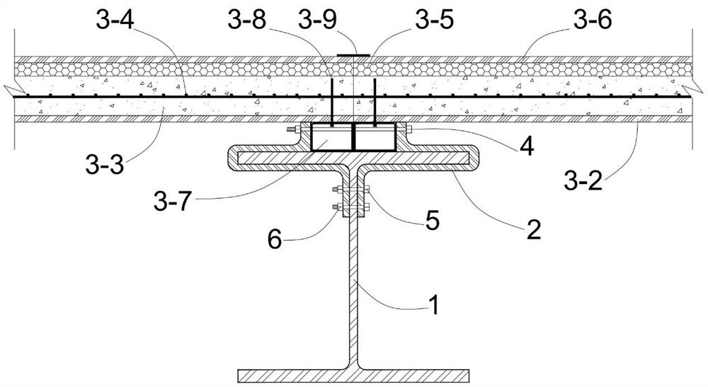
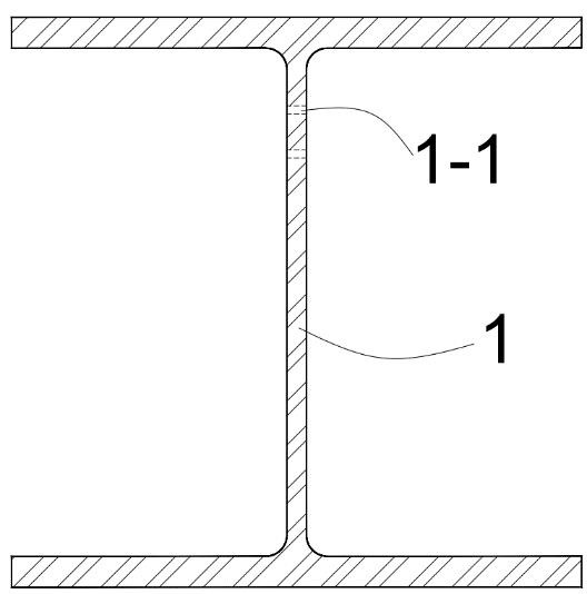
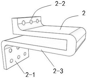
[0051] A connection structure between a steel frame lightweight roof panel and an H-shaped steel beam, including an H-shaped steel beam 1, a connector 2, and a steel frame lightweight roof panel 3, the connector 2 includes a first connecting section 2-1, a second The second connecting section 2-2, the third connecting section 2-3, the first connecting section 2-1, the second connecting section 2-2, and the third connecting section 2-3 enclose a half wing with the H-shaped steel beam 1 The outer edge matches the structure, the first connecting section 2-1 is set vertically upwards, and the two connecting pieces 2 are arranged on both sides of the top flange of the H-shaped steel beam 1, and the first connecting section 2 of the two connecting pieces 2 Two hollow square steel frames 3-7 are arranged between -1 and the two hollow square steel frames 3-7 occupy the area between the two first connecting sections 2-1. The two first connecting sections 2-1 and the hollow square steel...


PUM


Abstract

The invention discloses a connecting structure of a steel frame light roof panel and an H-shaped steel beam, and belongs to the technical field of building structure connection. The connecting structure comprises the H-shaped steel beam, two connecting pieces and the steel frame light roof panel, the two connecting pieces are oppositely arranged on two sides of a top flange of the H-shaped steel beam, a hollow square steel frame is arranged between first connecting sections of the two connecting pieces, the two first connecting sections and the hollow square steel frame are fixedly connected through long high-strength bolts which transversely penetrate through the hollow square steel frame, and a third connecting section is vertically arranged downwards and fixedly connected with a web of the H-shaped steel beam through short high-strength bolts. The connecting structure of the connecting piece is adopted, the situation that the flange strength of the H-shaped steel beam is weakened due to the fact that holes are formed in the flanges of the H-shaped steel beam is avoided, meanwhile, clamping grooves of the connecting piece are connected with the high-strength bolts and the flanges of the H-shaped steel beam, tight connection between the steel frame light roof panel and the H-shaped steel beam is guaranteed, and the integrity of the structure is improved.

Description

technical field [0001] The invention belongs to the technical field of building structure connection, and in particular relates to a connection structure between a steel frame light roof panel and an H-shaped steel beam. Background technique [0002] Prefabricated steel structure buildings are promoting the rapid development of the construction industry, because of their advantages such as convenient installation, fast construction speed, saving construction time and construction costs, and recyclable resources. It is a green and environmentally friendly building structure model. The future research direction of industrialization development. [0003] Prefabricated steel structure buildings have the following advantages: ①Steel structures are energy-saving and environmentally friendly. Steel can be recycled and reused; ②Steel structure has better seismic performance. The steel structure is light in weight and high in strength, which can effectively reduce the seismic force...

Claims


Application Information

Patent Timeline
Patent Type & Authority Applications(China)
IPC IPC(8): E04B5/00E04B5/02E04B5/10E04C2/292E04C2/38
CPCE04B5/00E04B5/02E04B5/10E04C2/292E04C2/384
Inventor 王凯张延年谷凡
Owner SHENYANG JIANZHU UNIVERSITY
Learn More