Display control card, receiving card array as well as relevant system and method

A display control card and receiving card technology, which is applied to TV system components, static indicators, TVs, etc., and can solve problems such as image out-of-sync

Active Publication Date: 2014-12-31
XIAN NOVASTAR TECH
View PDF1 Cites 1 Cited by
  • Summary
  • Abstract
  • Description
  • Claims
  • Application Information

AI Technical Summary

Problems solved by technology

Although this method avoids the instability of the field frequency, because each receiving card in the receiving card array is processed separately, the images between the receiving cards are not synchronized

Method used


Image

  • Display control card, receiving card array as well as relevant system and method
  • Display control card, receiving card array as well as relevant system and method
  • Display control card, receiving card array as well as relevant system and method

Examples


no. 1 example

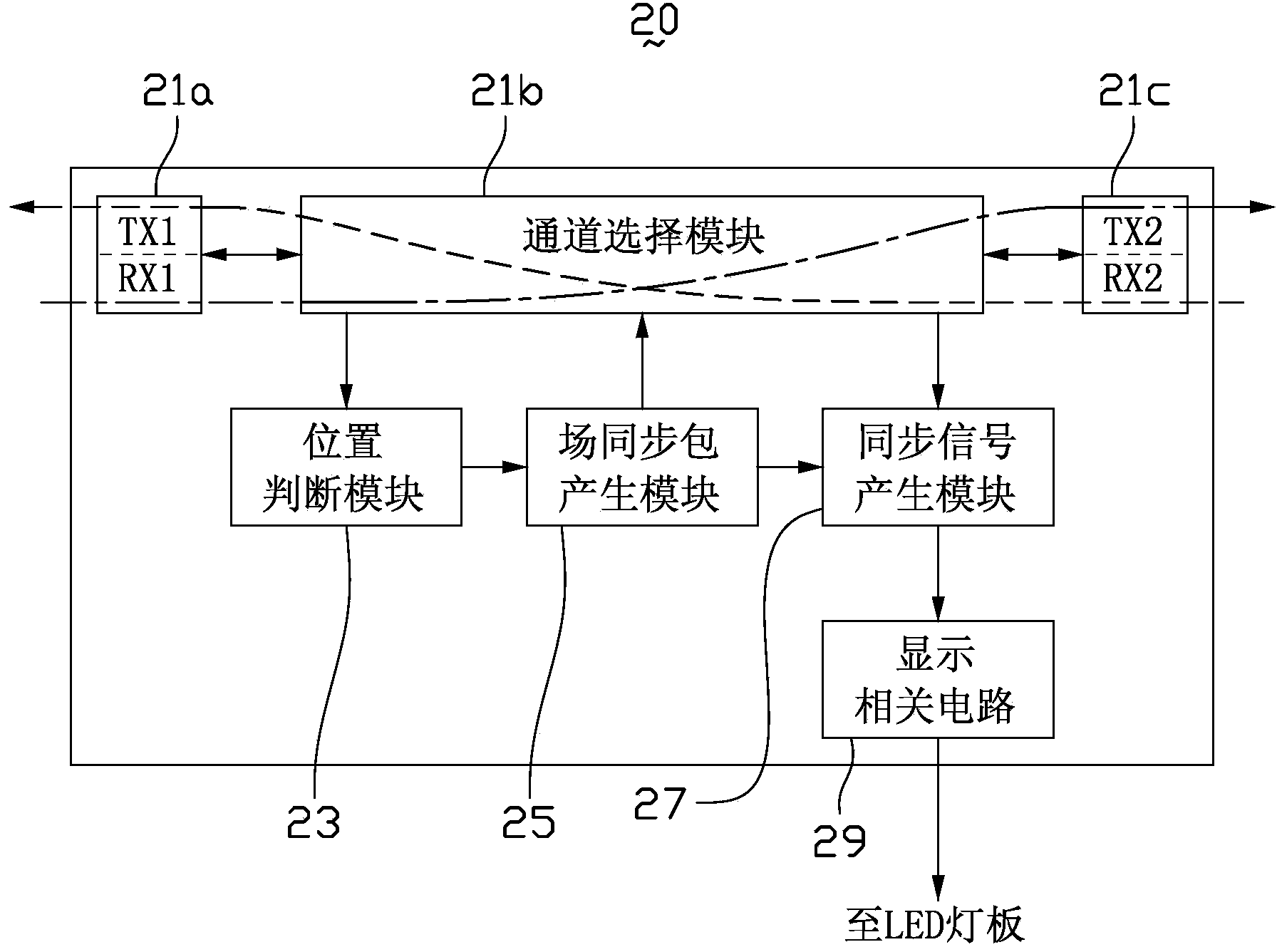
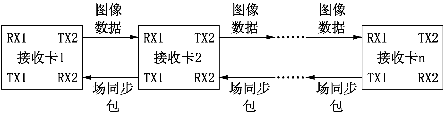
[0029] see figure 2 and image 3 ,in figure 2 It is a schematic diagram of the modules of the display control card in the first embodiment of the present invention, image 3 It is a schematic diagram of the receiving card array of the first embodiment of the present invention. Such as figure 2 As shown, the display control card 20 includes transceiver modules 21a, 21c, a channel selection module 21b, a position judgment module 23, a field synchronization packet generation module 25, a synchronization signal generation module 27 and a display related circuit 29. In this embodiment, the display control card 20 is a receiving card, such as image 3 Receiving card 1, receiving card 2, ..., a certain receiving card in receiving card n, but the present invention is not limited thereto, and it can also be other display control cards equipped with receiving card functions.

[0030]Wherein, the transceiver module 21a includes a sending unit TX1 and a receiving unit RX1; similar...

no. 2 example

[0036] see Figure 4 , which is a schematic diagram of a receiving card array according to the second embodiment of the present invention. exist Figure 4 Among them, the first receiving card 1 in the receiving card array is the receiving card designated to generate field synchronous packets, and it can judge whether it is the first receiving card by setting the position judgment module 23 on each receiving card 1-n to monitor the data of RX1 A receiving card 1 . In addition, in Figure 4 In the shown receiving card array, each receiving card 1-n can have figure 2 The module structure shown. Additionally, with image 3 The main difference is that: the image data for display and the field synchronization packet are both transmitted through the downlink channel, that is, the field synchronization packet is transmitted through the channel where RX1 and TX2 are located.

no. 3 example

[0038] see Figure 5 , which is a schematic diagram of a receiving card array according to the third embodiment of the present invention. exist Figure 5 Among them, a certain receiving card between the first and the last receiving card in the receiving card array, such as receiving card 2, is the receiving card designated to generate field synchronization packets, that is, by setting the receiving card on each receiving card 1-n The location judging module 23 simultaneously monitors the data of RX1 and RX2 to judge whether it is the second receiving card 2 . In addition, in Figure 5 In the shown receiving card array, each receiving card 1-n can have figure 2 The module structure shown. Additionally, with image 3 The difference mainly lies in: for the receiving card before receiving card 2, such as receiving card 1, its display image data is transmitted by using the downlink channel (that is, the transmission channel where RX1 and TX2 are located), and the field synchr...


PUM


Abstract

The invention relates to a display control card, a receiving card array, a sending-card-free LED (light emitting diode) synchronous control system, a synchronous signal generating method and an LED display control method. The display control card comprises a transmission channel, a position judging module, a field synchronous packet generating module and a synchronous signal generating module, wherein the position judging module is used for judging whether field synchronous packets are input from the transmission channel or not; the field synchronous packet generating module is used for generating the field synchronous packets and providing the field synchronous packets to the transmission channel to be externally output when no field synchronous packet is input from the transmission channel; the synchronous signal generating module is used for generating synchronous signals according to the field synchronous packets generated by the field synchronous packet generating module when no field synchronous packet is input from the transmission channel, or is used for generating synchronous signals according to the field synchronous packets input from the transmission channel when the field synchronous packets are input from the transmission channel. The specific display control card is used for generating the field synchronous packets, in addition, the field synchronous packets are provided for other display control cards to be used, and the problems of field synchronous signal generation instability and asynchrony can be solved.

Description

technical field [0001] The present invention relates to the field of display technology, such as the field of LED display technology, in particular to a display control card, a receiving card array, an LED synchronous control system without a sending card, a synchronous signal generation method, and an LED display control system. method. Background technique [0002] LED synchronous control system without sending card mainly includes PC and receiving card array. Compared with synchronous control system with sending card, LED synchronous control system without sending card does not have special sending card equipment, thus reducing the cost of the control system. However, because there is no sending card device, there is a problem with the synchronization of the receiving card, so that the LED screen display will appear out of sync and cause image tearing. Therefore, a synchronization signal must be generated so that each receiving card in the receiving card array synchronou...

Claims


Application Information

Patent Timeline
Patent Type & Authority Applications(China)
IPC IPC(8): H04N5/04H04N5/06G09G3/32
Inventor 刘德福王伙荣
Owner XIAN NOVASTAR TECH
Why Eureka
Try Eureka