Electric apparatus

A technology for electrical equipment and electrical components, which can be used in electrical equipment structural parts, electrical components, heat exchange equipment, etc., and can solve problems such as increased pressure drop, energy consumption noise, etc.

Active Publication Date: 2014-12-31
ABB (SCHWEIZ) AG
View PDF2 Cites 0 Cited by
  • Summary
  • Abstract
  • Description
  • Claims
  • Application Information

AI Technical Summary

Problems solved by technology

However, this requires larger fans and increases pressure drop, power consumption, and noise

Method used


Image

  • Electric apparatus
  • Electric apparatus
  • Electric apparatus

Examples


Embodiment Construction

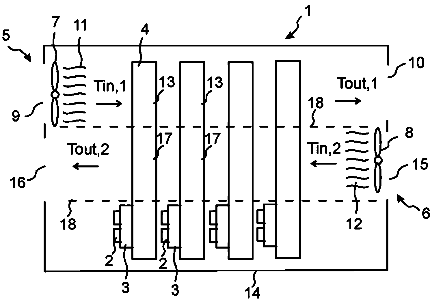
[0014] figure 1 A first embodiment of the device is shown. The illustrated electrical device 1 may be a motor drive, such as a frequency converter, supplying electrical power to an electric motor.

[0015] In the example shown, the electrical component 2 is attached to the cooling element 4 via the base plate 3 . However, a substrate is not required in all embodiments. Heat generated by the electrical components during use is conducted to the cooling element 4 . In the example shown, a first end of the substantially parallel cooling element 4 is provided with the electrical component 2 , while an opposite second end of the cooling element is arranged in the air flow.

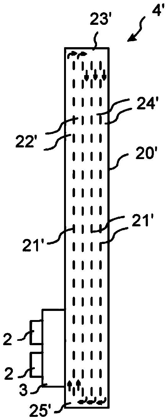
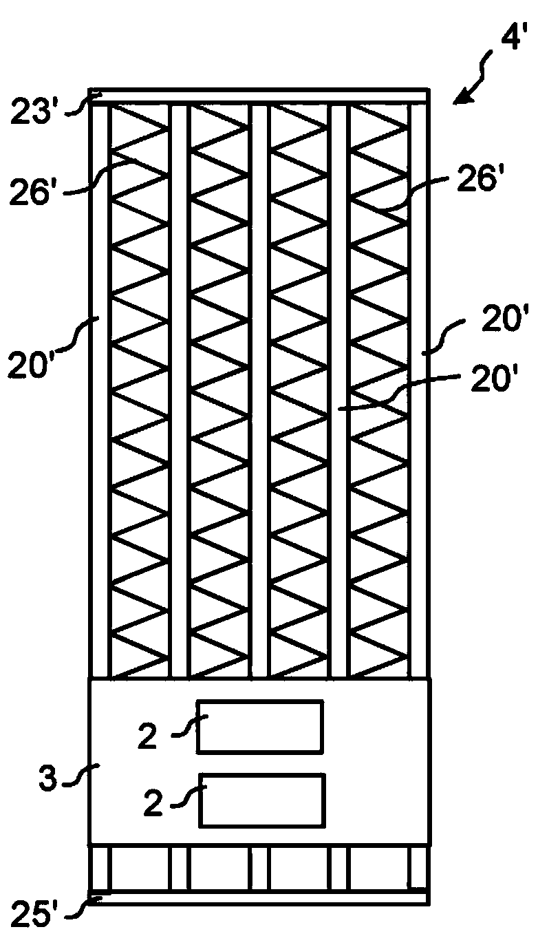
[0016] The cooling element 4 can be made of, for example, aluminum or other suitable material with excellent thermal conductivity. In its simplest form, the cooling element 4 may consist of cooling fins whose metallic material, for example, conducts heat from the electrical component 2 to the air flow. Howe...


PUM


Abstract

The invention relates to an electric apparatus (1) comprising at least two cooling elements (4) and a first fan arrangement (5) for cooling the at least two cooling elements (4) with a first air flow (11). In order to obtain an efficient cooling solution the electric apparatus (1) comprises a second fan arrangement (6) for cooling the at least two cooling elements (4) with a second air flow (12). The second fan (6) arrangement passes the second air flow (12) in a different flow direction as compared to the first air flow (11), and the first (11) and second air flows (12) are arranged to cool different parts (13, 17) of the at least two cooling elements (4).

Description

technical field [0001] The invention relates to an electrical device and in particular to a solution for cooling an electrical device. Background technique [0002] Solutions are known previously which utilize fan structures to provide an air flow via at least two cooling elements to which electrical components are attached, such that the cooling elements receive the thermal load generated by the electrical components. The air flow passing through the cooling element receives the thermal load from the cooling element and sends the thermal load to the environment. [0003] A disadvantage of the above solution is that different cooling elements receive different amounts of cooling. The initially relatively cool air passes through the first cooling element where it is heated as it cools the first cooling element. Consequently, subsequent cooling elements in the direction of air flow will receive air that has been heated by preceding cooling elements. In embodiments comprisin...

Claims


Application Information

Patent Timeline
Patent Type & Authority Applications(China)
IPC IPC(8): H05K7/20
CPCF28D15/0233F28D15/0266F28F13/06H05K7/20336
Inventor 弗朗切斯科·阿戈斯蒂尼达尼埃莱·托雷辛马蒂厄·哈贝特布鲁诺·阿戈斯蒂尼
Owner ABB (SCHWEIZ) AG
Why Eureka
Try Eureka