
Electronic component installation device and electronic component installation method

An electronic component installation, electronic component technology, applied in the direction of electrical components, electrical components, etc., can solve the problems of no setting, complex structure, inability to properly cut off the empty supply belt with curling, and achieve the effect of eliminating blocking or winding

Active Publication Date: 2014-12-31
JUKI CORP
View PDF6 Cites 2 Cited by
  • Summary
  • Abstract
  • Description
  • Claims
  • Application Information

AI Technical Summary

Problems solved by technology

[0007] In the technology described in the above-mentioned Patent Document 1, since there is no mechanism for smoothly introducing the empty supply tape after taking out the electronic components between the cutters, it may not be possible to cut the curled empty supply tape properly.
[0008] In addition, in the technology described in the above-mentioned Patent Document 2, although a mechanism for introducing an empty supply tape between the cutters is provided, the structure is complicated and the manufacturing cost during assembly is high.

Method used


Image

  • Electronic component installation device and electronic component installation method
  • Electronic component installation device and electronic component installation method
  • Electronic component installation device and electronic component installation method

Examples


Embodiment Construction

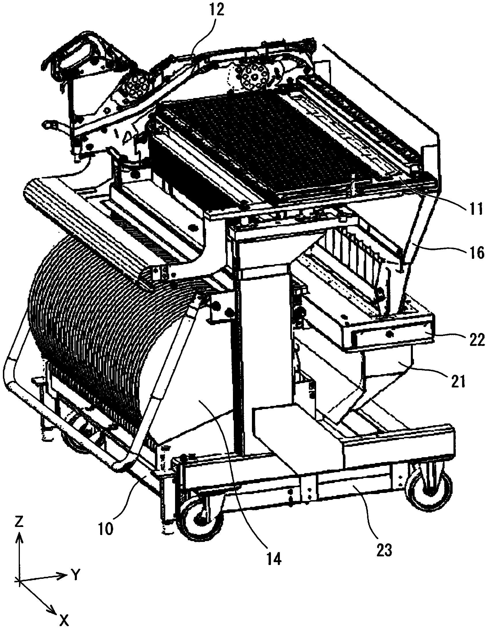
[0030] Hereinafter, embodiments of the present invention will be described based on the drawings. figure 1 It is a perspective view of the collective exchange stand showing a state mounted on the electronic component mounting device of the present embodiment, omitting a part of the main body of the mounting device.

[0031] The mass exchange stand 10 can be mounted to a predetermined position of the apparatus main body by moving forward in the horizontal direction, and can be removed by moving backward in the horizontal direction. A plurality of tape feeders 12 (in the figure 1 only one is shown).

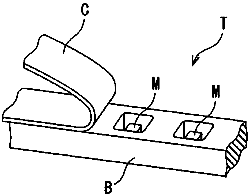
[0032] The tape feeder 12 feeds the carrier tape wound on the lower reel 14 in the downstream direction. like figure 2 As shown, the carrier tape T is composed of a strip-shaped base tape B and an outer cover tape C. A plurality of recesses are provided on the base tape B at intervals, and electronic components M are housed in the respective recesses. In addition, a cover tap...


PUM


Abstract

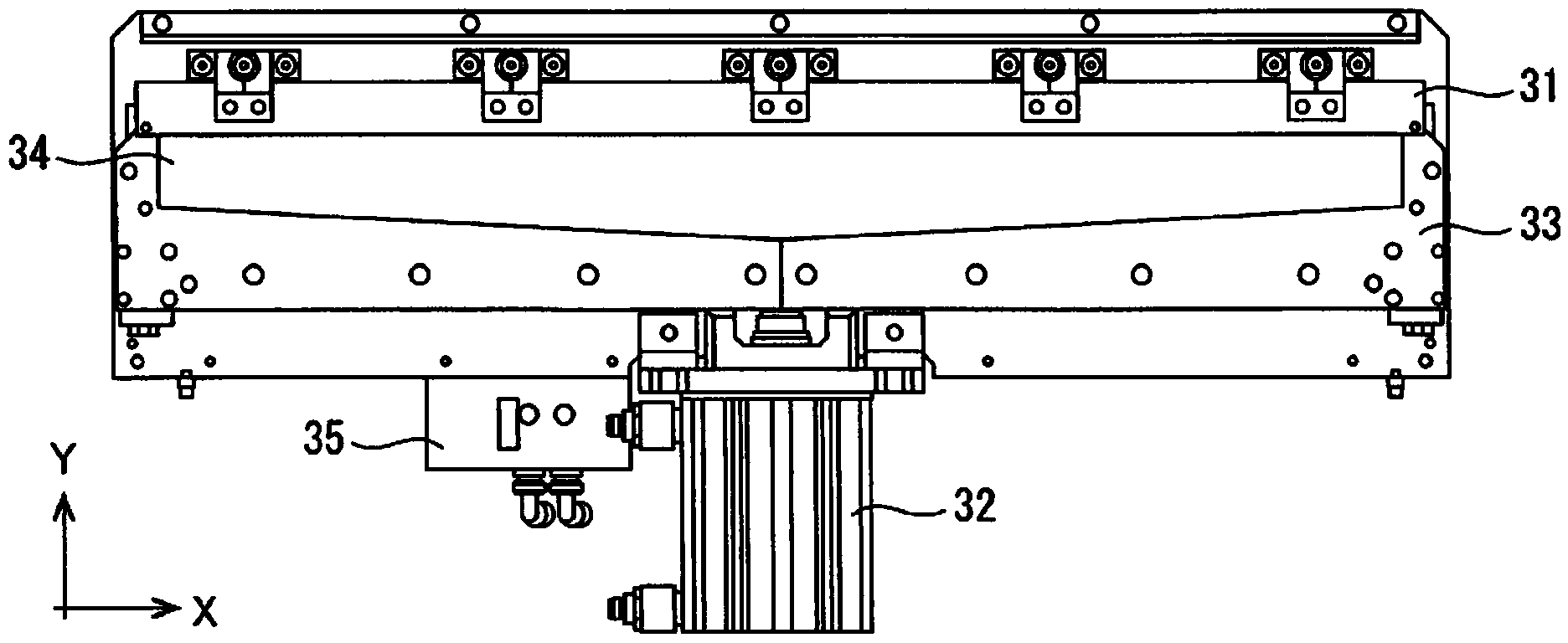
The invention provides an electronic component installation device and an electronic component installation method, which can reliably supply an empty feeder belt for a feeder belt cutter and suitably cut off the empty feeder belt. An empty feeder belt is send out from a downstream end in a feeder belt feeding direction of a belt type supplier (12), and is lead to a feeder belt cutter part (22) arranged in a lower side by a guiding part (16). In addition, on the downstream of guiding, air is blown out towards the lower end part of the empty feeder belt from an upper side direction, and a fixed blade (31) and a movable blade (33) capable of moving in a horizontal direction cut the empty feeder belt.

Description

technical field [0001] The present invention relates to an electronic component mounting device and an electronic component mounting method for mounting components supplied from an electronic component supply device on a substrate. Background technique [0002] As a conventional electronic component mounting apparatus, the technique described in patent document 1 exists, for example. This technique is to continuously operate the air supply source while the electronic component mounting apparatus is operating. Then, the air supplied from the air supply source is evenly blown from above to below to the interior of the cutter unit for cutting the empty supply tape from which the electronic components have been taken out. Thereby, it is avoided that fine tape scraps and the like generated when the empty supply tape is cut by the movement of the cutter stay. [0003] In addition, since the component supply tape is wound around the reel, it is curled and always goes out of the g...

Claims


Application Information

Patent Timeline
Patent Type & Authority Applications(China)
IPC IPC(8): H05K13/04
Inventor 小浜次郎
Owner JUKI CORP
Learn More