
Hospital bed brake warning mechanism and hospital bed with same

A brake mechanism and technology for hospital beds, which can be used in hospital beds, hospital equipment, medical science, etc., can solve the problems of high cost, sliding of hospital beds, and no installation, etc., and achieve the effect of convenient use, sensitive braking, and simple structure

Active Publication Date: 2015-01-07
江西美格尔医疗设备有限公司
View PDF5 Cites 4 Cited by
  • Summary
  • Abstract
  • Description
  • Claims
  • Application Information

AI Technical Summary

Problems solved by technology

[0002] At present, in hospitals, in order to facilitate the transfer of patients, sick beds with casters are generally used. Some of the existing sick beds with casters do not have a brake mechanism, although some have a brake mechanism, but the cost is relatively high. The biggest defect is that there is no obvious sign or warning device to inform the braking state of the hospital bed, so that during use, neither the nursing staff nor the patient knows whether the hospital bed is in the braking state
If the bed is in the released state, when the patient gets on and off the bed, or when someone leans on the bed, it will cause the bed to slide, which will easily cause people to fall and cause unnecessary injuries

Method used


Image

  • Hospital bed brake warning mechanism and hospital bed with same
  • Hospital bed brake warning mechanism and hospital bed with same

Examples


Embodiment Construction

[0016] The present invention will be described in further detail below in conjunction with the accompanying drawings and specific embodiments. The following embodiments are explanations of the present invention, and the present invention is not limited to the following embodiments.

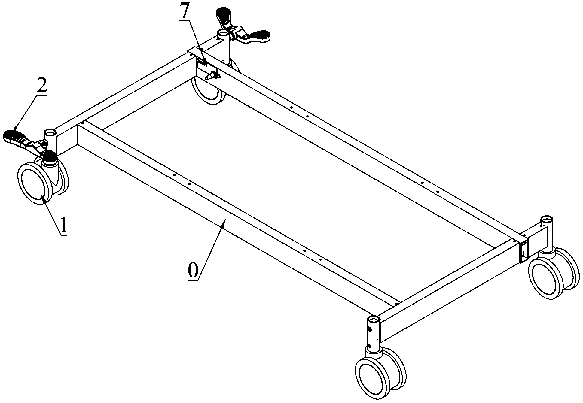
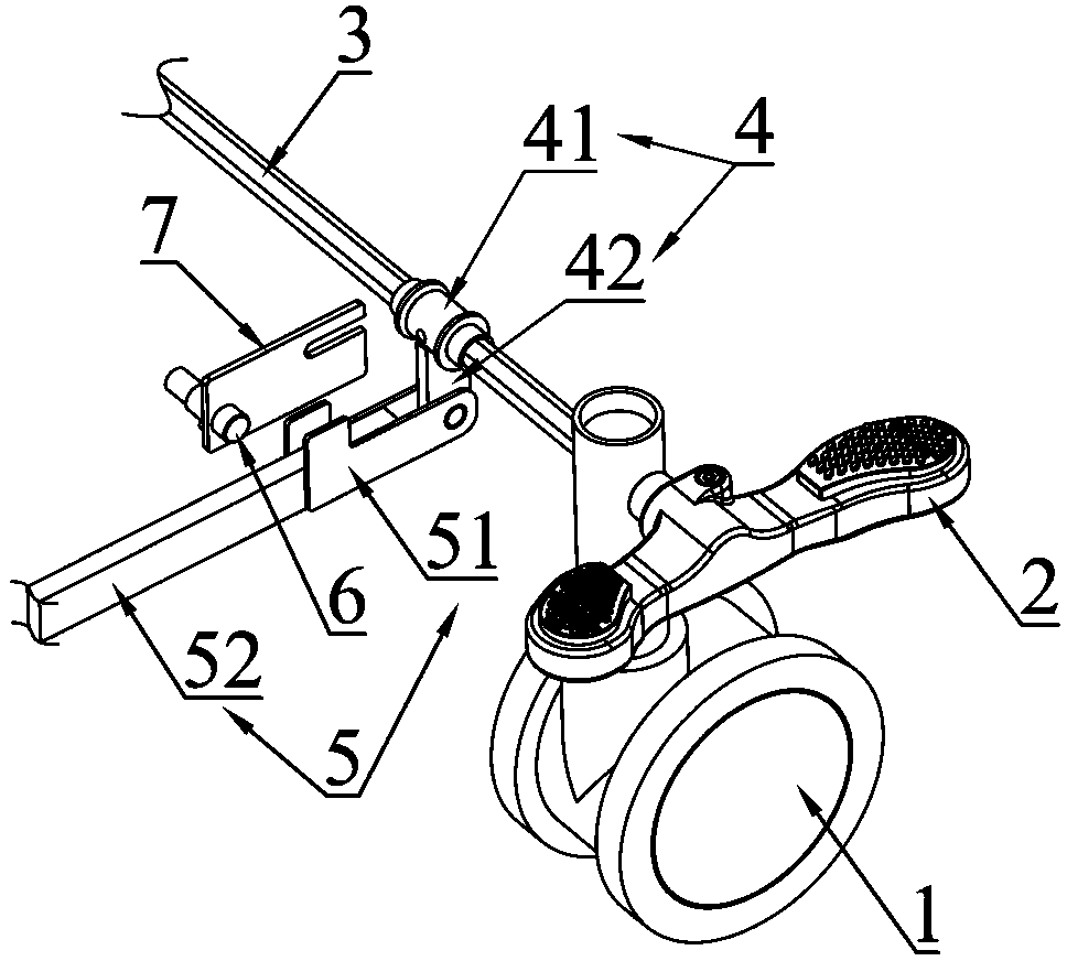
[0017] see figure 1 with figure 2 As shown, the figure is a structural schematic diagram of an embodiment of the hospital bed brake warning mechanism provided by the present invention. The bed brake warning mechanism in this embodiment is composed of two functional parts, one is a brake mechanism, and the other is a warning mechanism.

[0018] The brake mechanism includes a central control pedal 2, a hexagonal rod 3, a pendulum piece 4 and a central control connecting rod 5; wherein, the hexagonal rod 3, the pendulum piece 4 and the central control connecting rod 5 are all arranged in the inner cavity of the bed frame 0; the so-called hexagonal Rod 3 refers to a rod-shaped object with a regular...


PUM


Abstract

The invention provides a hospital bed brake warning mechanism and a hospital bed with the same and relates to the technical field of brake devices of hospital beds. The hospital bed brake warning mechanism and the hospital bed aim at solving the problems that the existing wheel hospital beds are high in cost and free of warning function. The hospital bed brake warning mechanism comprises central control pedal plates, hexagonal rods, swing pieces and a central control connecting rod; the hexagonal rods are arranged on two castors of a hospital bed in a straddled mode respectively; the two central control pedal plates sleeve two ends of the hexagonal rods respectively; each central control pedal plate is provided with a stamping portion for a human foot to stamp so as to enable the hexagonal rods to rotate; the central control connecting rod is perpendicularly arranged between the two hexagonal rods; two ends of the central control connecting rod are connected with the hexagonal rods through the swing pieces respectively; each swing piece is formed by a hexagonal sleeve and a connecting piece; each hexagonal sleeve sleeves the corresponding hexagonal rod through a hexagonal inner hole formed inside the hexagonal sleeve; one end of each connecting piece is fixedly connected with the corresponding hexagonal sleeve; the other end of each connecting piece is hinged to the central control connecting rod; the hospital bed brake warning mechanism also comprises an proximity sensor and a warning device; the proximity sensor is used for detecting the position of the central control connecting rod. According to the hospital bed brake warning mechanism, the accidental injury to the personnel due to the fact that the hospital bed is located in the non-braking state can be effectively avoided.

Description

technical field [0001] The invention relates to the technical field of braking devices for hospital beds, in particular to a braking device with a warning function and a hospital bed provided with the device. Background technique [0002] At present, in hospitals, in order to facilitate the transfer of patients, sick beds with casters are generally used. Some of the existing sick beds with casters do not have a brake mechanism, although some have a brake mechanism, but the cost is relatively high. The biggest defect is that there is no obvious sign or warning device to inform the braking state of the hospital bed, so that during use, both the nursing staff and the patient do not know whether the hospital bed is in the braking state. If the bed is in the release state, when the patient gets on and off the bed, or when someone leans on the bed, the bed will slide, which will easily cause people to fall and cause unnecessary injuries. Contents of the invention [0003] Aimin...

Claims


Application Information

Patent Timeline
Patent Type & Authority Applications(China)
IPC IPC(8): A61G7/05A61G7/00
Inventor 彭丹
Owner 江西美格尔医疗设备有限公司
Learn More