
A rolling machine for circular steel rings of cement poles

A cement pole and ring-shaped technology, applied in metal processing equipment, safety equipment, manufacturing tools, etc., can solve the problems of inability to directly weld and form, high cost of processing equipment, large investment in equipment, etc., to achieve simple and safe operation, The effect of simple structure and convenient operation

Active Publication Date: 2016-08-24
CHUZHOU CHUANQI CEMENT PROD
View PDF5 Cites 0 Cited by
  • Summary
  • Abstract
  • Description
  • Claims
  • Application Information

AI Technical Summary

Problems solved by technology

In the existing spheronizing machine, the roller shaft is mainly cantilever type, and the rolled product has a spiral structure, and the circularity of the rolled product is poor, so it cannot be directly welded and formed
There are also large-scale rolling machines, the roller shaft of which mainly adopts a simply supported beam structure, and mainly processes steel plate rings with large diameters (more than 0.5m in diameter), and generally leaves a large gap for taking out the roller from the roller shaft. Pressed semi-finished products still need follow-up processing before they can be welded into circular rings, and the cost of processing equipment is relatively high. It is suitable for large-scale cement pole factories. For small cement pole factories, equipment investment is relatively large
However, the quality and strength of the circular steel plate ring produced by the cast steel casting method are not as good as those produced by the steel plate rolling method.

Method used


Image

  • A rolling machine for circular steel rings of cement poles
  • A rolling machine for circular steel rings of cement poles
  • A rolling machine for circular steel rings of cement poles

Examples


Embodiment Construction

[0025] The following will clearly and completely describe the technical solutions in the embodiments of the present invention with reference to the accompanying drawings in the embodiments of the present invention. Obviously, the described embodiments are only some, not all, embodiments of the present invention. Based on the embodiments of the present invention, all other embodiments obtained by persons of ordinary skill in the art without creative efforts fall within the protection scope of the present invention.

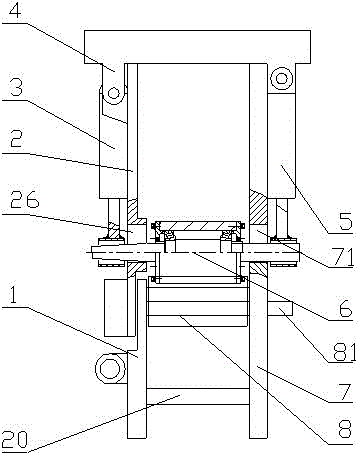
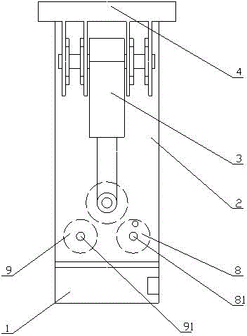
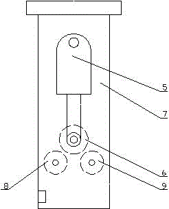
[0026] As embodiment one of the present invention, a rolling machine for circular steel rings of cement poles is provided, such as figure 1 , figure 2 , image 3 , Figure 4 As shown, the left support 1, the left movable plate 2, the left hydraulic cylinder 3, the beam plate 4, the right hydraulic cylinder 5, the movable pinch wheel assembly 6, the right bracket 7, the front pinch wheel assembly 8, the rear pinch wheel assembly 9, and the Plate 20, characterize...


PUM


Abstract

The invention provides an annular steel plate ring roller press of a concrete pole. The annular steel plate ring roller press is composed of a support component, a movable wheel component, a front pressing wheel component and a rear pressing wheel component, and is characterized in that the movable wheel component, the front pressing wheel component and the rear pressing wheel component are sequentially arranged on the support component, one end of the support component is provided with an open movable support; the movable wheel component is driven by a hydraulic cylinder, so as to realize upward and downward movement; the front and rear pressing wheel components are respectively connected with an outside motor so as to realize initiative selection movement. According to the annular steel plate ring roller press provided by the invention, by adopting a way of rolling to form a circle, an annular steel plate ring needed by the concrete pole can be rolled and processed quickly and efficiently, therefore the annular steel plate ring roller press has the characteristics of being simple in structure, convenient to operate and the like; furthermore, the annular steel plate ring roller press is provided with a four-link mechanism with the functions of locking and anti-rotating, therefore materials can be simple and safe to take.

Description

technical field [0001] The invention relates to the field of cement pole manufacturing equipment, in particular to forming equipment for processing circular steel rings of cement poles. Background technique [0002] Assembled cement poles (more than 8 meters in length) are generally assembled by butt joints of two or more flange-type or steel-plate ring-type cement poles. The production efficiency and cost of flange plates or steel rings directly affect production efficiency and cost. Wherein, the flange plate or the steel plate ring all contain circular steel plate rings, and its production methods mainly include steel plate rolling method and cast steel casting method. In the existing rounding machine, the roller shaft is mainly cantilever type, and the rolled product has a spiral structure, and the roundness of the rolled product is poor, so it cannot be directly welded and formed. There are also large-scale rolling machines, the roller shaft of which mainly adopts a si...

Claims


Application Information

Patent Timeline
Patent Type & Authority Patents(China)
IPC IPC(8): B21D5/14B21D55/00B21D45/00
CPCB21D5/14B21D45/00B21D55/00
Inventor 廖玉松方先龙谭志银朱厚奇翟德所
Owner CHUZHOU CHUANQI CEMENT PROD
Learn More