Semi-automatic graduated steel bar bending machine

A steel bar bending and scale line technology, which is applied in metal processing, metal processing equipment, manufacturing tools, etc., can solve the problems of not being able to control the bending angle of steel bars well and narrow application range, and achieve stable clamping, size and position design Reasonable, non-slip effect

Inactive Publication Date: 2016-03-02
SICHUAN DINGRUI HYDRAULIC EQUIP MFR
View PDF7 Cites 2 Cited by
  • Summary
  • Abstract
  • Description
  • Claims
  • Application Information

AI Technical Summary

Problems solved by technology

However, this steel bar bending machine cannot control the bending angle of the steel bar very well, and in addition, it can only bend the steel bar to a certain fixed value of the bending radius of curvature, so the scope of application is narrow

Method used


Image

  • Semi-automatic graduated steel bar bending machine
  • Semi-automatic graduated steel bar bending machine
  • Semi-automatic graduated steel bar bending machine

Examples


Embodiment 1

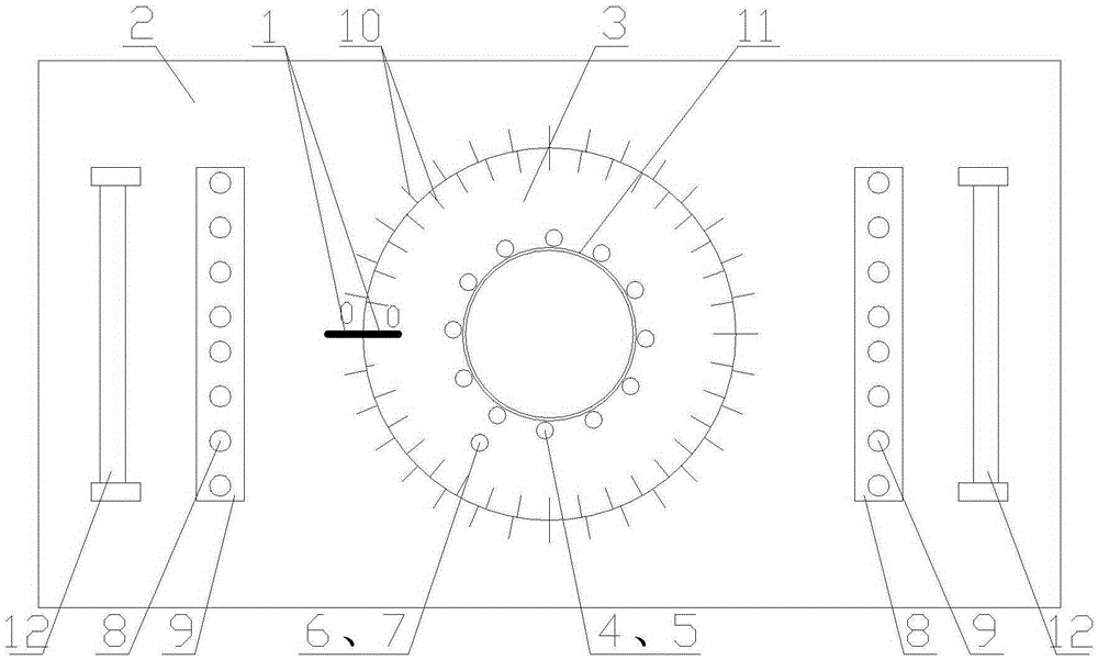
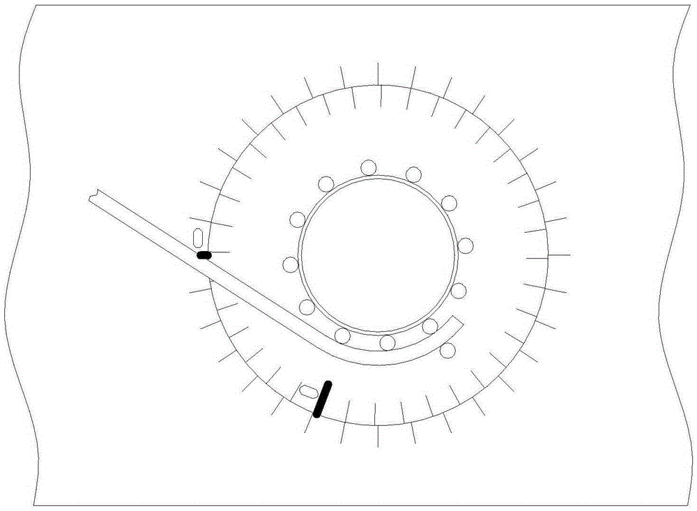
[0028] A semi-automatic graduated line steel bar bending machine such as figure 1 As shown, it includes a machine tool, the upper part of the machine tool is provided with a work disk 2, and the work disk 2 is connected with the machine tool. A rotating disk 3 is arranged at the center of the working disk 2, and the rotating disk 3 is connected with a power mechanism inside the machine tool, and the power mechanism can drive the rotating disk 3 to rotate around its own axis. A number of positioning shaft holes 5 and clamping shaft holes 7 are evenly distributed on the rotating disc 3 along the circumferential direction of the rotating disc 3, and the distance between the positioning shaft holes 5 and the clamping shaft holes 7 is adapted to the diameter of the steel bar to be bent , a number of positioning shaft holes 5 are distributed in a circle on the rotating disk 3, and the center of the circularly distributed positioning shaft holes 5 coincides with the center of the rot...

Embodiment 2

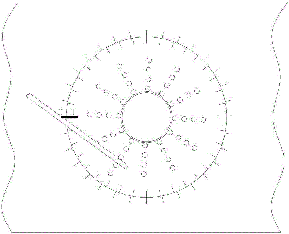
[0031] On the basis of Embodiment 1, the distribution of several positioning shaft holes 5 on the rotating disk 3 is set as several concentric circles, so that several positioning shaft holes 5 form multiple circles of positioning shaft holes 5 on the rotating disk 3, and The multi-circle positioning shaft holes 5 are concentric circles with each other. When the semi-automatic scale line steel bending machine is working, the positioning shaft hole 5 is only placed in a certain circle of the positioning shaft hole 5 located at a certain radius value, and there is no need to place the positioning shaft 4 on all the positioning shaft holes 5. In this Place the clamping shaft 6 in the clamping shaft hole 7 at the outer position of the positioning shaft hole 5 of the ring. The positioning shaft holes 5 form several concentric circles on the rotating disk 3, and the positioning shaft holes 5 located at different diameters can process steel bars with different bending radii, expandin...

Embodiment 3

[0033] Based on the first or second embodiment, the positioning shaft 4 is provided with a positioning collar 41 ; the clamping shaft 6 is provided with a clamping collar 61 . The positioning collar 41 is set on the positioning shaft 4, which can effectively prevent the steel bar from slipping during the bending process, ensuring the bending accuracy and bending quality of the semi-automatic scale line steel bar bending machine; the clamping shaft 6 is provided with a clamping collar 61 , which can further prevent the steel bar from slipping during bending.


PUM


Abstract

The invention discloses a semi-automatic scale mark reinforcing steel bar bending machine, relates to the technical field of reinforcing bar bending forming devices, and aims at providing the semi-automatic scale mark reinforcing steel bar bending machine with the accurate bending angle. According to the technical scheme, the semi-automatic scale mark reinforcing steel bar bending machine comprises a machine tool. A working disc connected with the machine tool is arranged at the upper portion of the machine tool. A rotating disc is arranged at the center of the working disc and connected with a power mechanism inside the machine tool and rotates around the axis of the rotating disc. A plurality of positioning shaft holes and a plurality of clamping shaft holes are evenly distributed in the rotating disc in the circumferential direction of the rotating disc. Positioning shafts and clamping shafts are correspondingly placed in the positioning shaft holes and the clamping shaft holes respectively. The working disc and the rotating disc are each provided with scale marks. The number of the scale marks on the rotating disc is larger than the number of the scale marks on the working disc. Through the position relation between the zero scale mark on the working disc and the zero scale mark on the rotating disc and through the scale marks, coinciding with the scale marks on the working disc, of the rotating disc, the rotation angle of the rotating disc can be obtained.

Description

technical field [0001] The invention relates to the technical field of steel bar bending and forming equipment, in particular to a steel bar bending machine. Background technique [0002] With the gradual development of my country's economic construction, large-scale construction projects are being carried out all over the country to build various residential buildings, office buildings, road works and other projects under construction. A large number of steel bars are bent. For the bending of steel bars, the traditional method is mainly to operate manually, but manual bending of steel bars not only consumes a lot of manpower, but also takes up a lot of construction space. Therefore, in order to solve this problem, there has been a commonly used steel bar processing machine in the prior art—a steel bar bending machine. The steel bar bending machine mainly includes a fuselage and a working disc that is positioned at the top of the fuselage and can rotate around its central ax...

Claims


Application Information

Patent Timeline
Patent Type & Authority Patents(China)
IPC IPC(8): B21F1/00B21C51/00
CPCB21C51/00B21F1/00
Inventor 陈安民
Owner SICHUAN DINGRUI HYDRAULIC EQUIP MFR
Why Eureka
Try Eureka