Lower knife shaft locking device of aluminum strip splitting machine

A slitting machine and shaft locking technology, which is applied in the direction of shearing devices, shearing machine accessories, metal processing equipment, etc., can solve problems such as radial runout and affecting the accuracy of slitting aluminum strips, and achieve the elimination of radial runout , simple structure, and the effect of improving the quality of slitting

Active Publication Date: 2015-01-07
登电集团铝加工有限公司
View PDF4 Cites 2 Cited by
  • Summary
  • Abstract
  • Description
  • Claims
  • Application Information

AI Technical Summary

Problems solved by technology

At present, one end of the lower knife shaft of the slitting machine is connected to the vertical plate in rotation, and the other end of the lower knife shaft is locked by the handle spring-type locking mechanism. Since the compression spring is used, even if an axial force is applied to the compression spring No matter how big it is, there is also a certain axial clearance of the lower cutter shaft during high-speed rotation. Since the lower cutter shaft is longer, radial runout will occur, which will affect the accuracy of cutting aluminum strips.

Method used


Image

  • Lower knife shaft locking device of aluminum strip splitting machine

Examples


Embodiment Construction

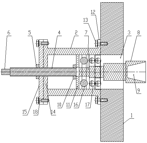
[0011] Such as figure 1 As shown, the lower cutter shaft locking device of the aluminum strip slitting machine of the present invention includes a vertical plate 1, the outer side of the vertical plate 1 is provided with a cylinder 2 arranged horizontally, and the vertical plate 1 is provided with a cylinder connected to the inner end of the cylinder 2. Through hole 3, the inner diameter of the through hole 3 is equal to the inner diameter of the cylinder body 2, the outer end of the cylinder body 2 is provided with a blocking plate, the center of the blocking plate is provided with a threaded hole, the threaded hole is horizontally threaded with a screw 4, and the screw 4 is threaded There is a fixed nut 5 that presses against the outer surface of the blocking plate, an operating head 6 is provided at the outer end of the screw rod 4, a bearing is provided inside the cylinder body 2, and the inner ring of the bearing is connected with a stepped shaft 7 that is small on the out...


PUM


Abstract

The invention discloses a lower knife shaft locking device of an aluminum strip splitting machine. The lower knife shaft locking device comprises a vertical plate, wherein a cylinder is horizontally arranged at the outer side of the vertical plate; a through hole communicated with the inner end of the cylinder is formed in the vertical plate; a plug plate is arranged at the outer end of the cylinder; the center of the plug plate is in horizontal threaded connection with a lead screw; the lead screw is in threaded connection with a fixed nut which presses against and matches the outer surface of the plug plate; an operation head is arranged at the outer end of the lead screw; a bearing is arranged in the cylinder; an inner ring of the bearing is connected with a step shaft in an interference fit manner; the inner end of the step shaft is coaxially connected with an ejection head; a conical hole is axially formed in the inner end of the ejection head; an outer ring of the bearing axially fits the inner wall of the cylinder in a sliding manner; the inner end of the lead screw is in threaded connection with a fastening nut; and the inner side of the fastening nut presses against and matches the outer side surface of the bearing through a pressure plate. The lower knife shaft locking device is reasonable in design and simple in structure, and axially ejects a lower knife shaft by adopting a lead screw locking manner without generating an axial gap, so that the radial jumping condition of the lower knife shaft in the high-speed rotating process is prevented, and the product splitting quality is improved.

Description

technical field [0001] The invention belongs to the technical field of aluminum strip processing and production, and in particular relates to a lower cutter shaft locking device of an aluminum strip slitting machine. Background technique [0002] The slitting machine is an important equipment in the production process of aluminum strip and aluminum foil. At present, one end of the lower knife shaft of the slitting machine is connected to the vertical plate in rotation, and the other end of the lower knife shaft is locked by the handle spring-type locking mechanism. Since the compression spring is used, even if an axial force is applied to the compression spring No matter how big it is, there is also a certain axial gap in the lower cutter shaft during high-speed rotation. Since the lower cutter shaft is longer, radial runout will occur, which will affect the accuracy of cutting aluminum strips. Contents of the invention [0003] In order to solve the deficiencies in the p...

Claims


Application Information

Patent Timeline
Patent Type & Authority Applications(China)
IPC IPC(8): B23D33/00
Inventor 胡冠奇毕书军牛荟晓苏孟杰袁文晓陈军歌
Owner 登电集团铝加工有限公司
Why Eureka
Try Eureka