Automatic screw locking machine

An automatic locking screw machine and screw technology, applied in the mechanical field, can solve the problems of locking failure, weak screw adsorption, and unreliable screws.

Inactive Publication Date: 2015-01-07
KUNSHAN FUXIN LIWEI AUTOMATION TECH
View PDF7 Cites 16 Cited by
  • Summary
  • Abstract
  • Description
  • Claims
  • Application Information

AI Technical Summary

Problems solved by technology

[0004] However, it is not reliable to use a magnetic screwdriver to pick up screws. With the long-term use of the magnetic screwdriver, the magnetic force of the magnetic screwdriver will gradually weaken, and the adsorption effect on the screw will become weaker and weaker, and the screw will appear on the magnetic screwdriver. The upper position is tilted and cannot be aligned with the screw hole, resulting in locking failure
Moreover, the magnetic screwdriver does not work for screws that are not affected by magnetism (such as stainless steel screws), and cannot lock the screws that are not affected by magnetism to the locking object

Method used


Image

  • Automatic screw locking machine
  • Automatic screw locking machine
  • Automatic screw locking machine

Examples


Embodiment Construction

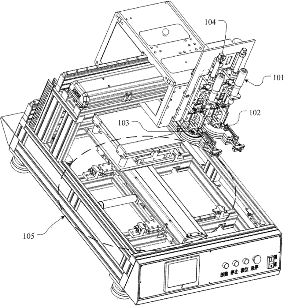
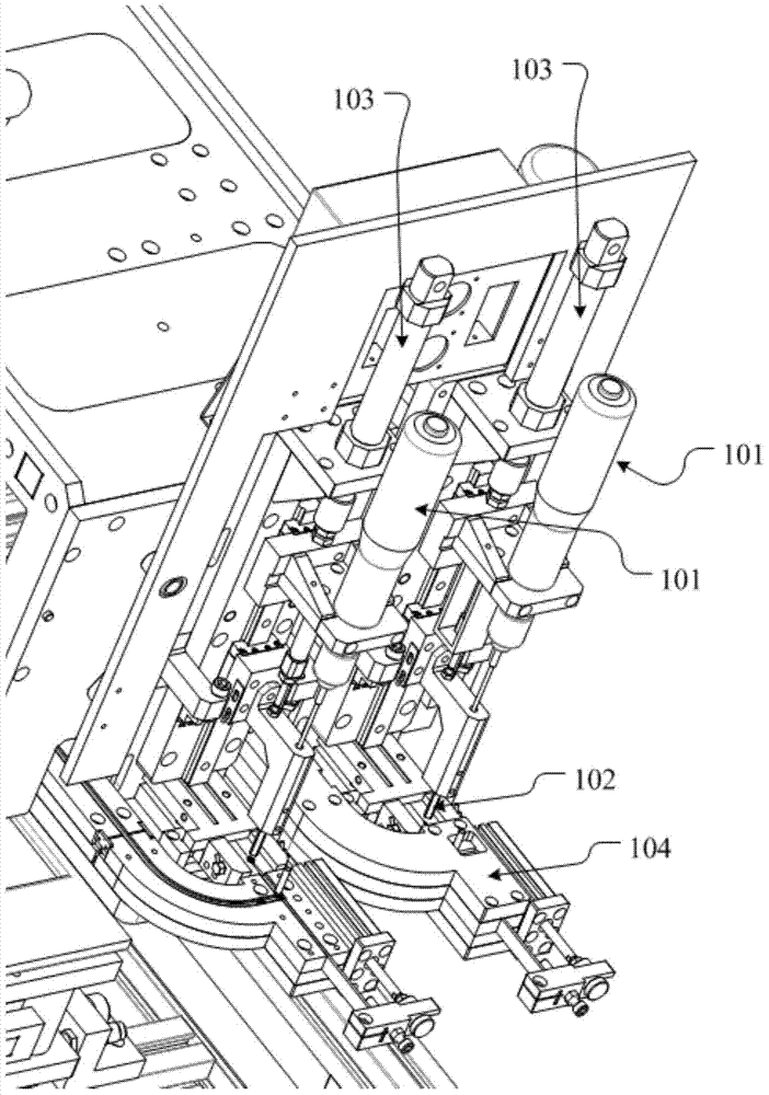
[0053] The embodiment of the present invention provides an automatic screw locking machine, which is used to avoid the situation where the screw position is tilted and cannot be aligned with the screw hole, resulting in locking failure, and there is no requirement for the magnetic properties of the screw, and various types of screws can be locked to the attached object.

[0054] In order to make the purpose, features and advantages of the present invention more obvious and understandable, the technical solutions in the embodiments of the present invention will be clearly and completely described below in conjunction with the accompanying drawings in the embodiments of the present invention. Obviously, the following The described embodiments are only some, not all, embodiments of the present invention. Based on the embodiments of the present invention, all other embodiments obtained by persons of ordinary skill in the art without making creative efforts belong to the protection...


PUM


Abstract

The embodiment of the invention discloses an automatic screw locking machine which is used for avoiding the situation that the screw position is inclined, and locking is failed due to the fact that the screw hole cannot be aligned. The automatic screw locking machine has no requirement for the magnetic force feature of screws, and various types of screws can be locked on a locked object. The automatic screw locking machine comprises an electric screw driver, an elastic clamp head, a clamping pneumatic claw, a locking hole sliding platform, a downwards-pressing air cylinder, and a program controller, wherein the elastic clamp head is arranged on the electric screw driver, the head of the elastic clamp head is provided with a clamping position for being clamped with a screw head of a screw in a matched mode, and the clamping position is used for fixing the screw to the elastic clamp head by clamping the screw head; the clamping pneumatic claw is used for clamping a screw rod of the screw to fix the screw; the locking hole sliding platform is used for conveying a screw hole required to be locked currently in the locked object to the position below the elastic clamp head by moving the locked object; the downwards-pressing air cylinder is used for driving the electric screw driver and the elastic clamp head on the electric screw driver to move downwards; the program controller is used for controlling the electric screw driver, the clamping pneumatic claw, the downwards-pressing air cylinder and the locking hole sliding platform through a preset operation process.

Description

technical field [0001] The invention relates to the field of machinery, in particular to an automatic screw locking machine. Background technique [0002] At present, screws are widely used, such as circuit boards, peripheral housings, internal structures of electronic equipment, etc., all of which require a large number of screws for structural fixing and locking. In order to improve the efficiency of production, the automatic locking screw machine came into being. [0003] The general practice of the current automatic screw locking machine is: control all the work processes through the program controller on the automatic locking screw machine, first use the magnetic screwdriver on the electric screwdriver to pick up the screw, and then send the screw hole that needs to be locked currently to the locked object. To the bottom of the magnetic screwdriver, the electric screwdriver is used to rotate and tighten the screw to the screw hole to complete the locking of a screw hol...

Claims


Application Information

Patent Timeline
Patent Type & Authority Applications(China)
IPC IPC(8): B23P19/06
CPCB23P19/069B23P19/006
Inventor 管贻纮
Owner KUNSHAN FUXIN LIWEI AUTOMATION TECH
Why Eureka
Try Eureka