Self-centering clamp

A self-centering fixture and self-centering technology, used in clamping, manufacturing tools, positioning devices, etc., can solve the problem of time-consuming, cumbersome operation, and reduce the speed of workpiece clamping and unloading, etc. question

Inactive Publication Date: 2015-01-07
深圳市速优精密机械有限公司
View PDF8 Cites 28 Cited by
  • Summary
  • Abstract
  • Description
  • Claims
  • Application Information

AI Technical Summary

Problems solved by technology

Since the four jaws of the four-jaw single-action chuck move independently, it can clamp parts that are not rotating bodies, but the center of rotation of the processing part must be aligned to coincide with the center of rotation of the lathe spindle during clamping. Turning can only be done after turning, resulting in time-consuming alignment of the four-jaw single-action chuck, cumbersome operation, and very inconvenient, reducing the speed of workpiece clamping and unloading, thereby reducing production efficiency and the practicability of the fixture

Method used


Image

  • Self-centering clamp
  • Self-centering clamp
  • Self-centering clamp

Examples


Embodiment 1

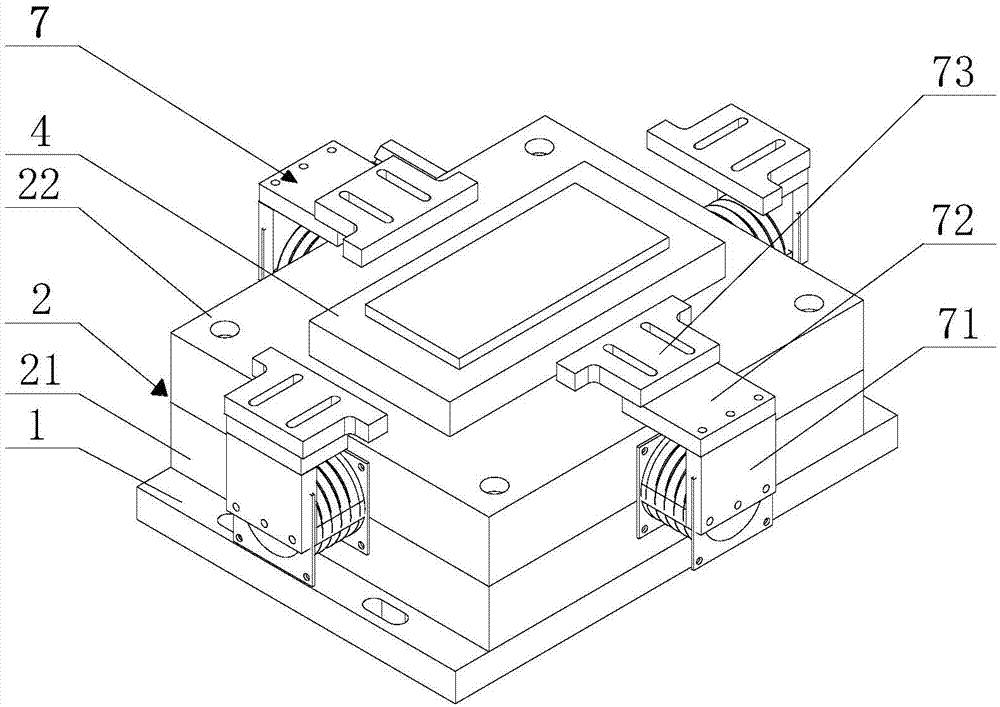
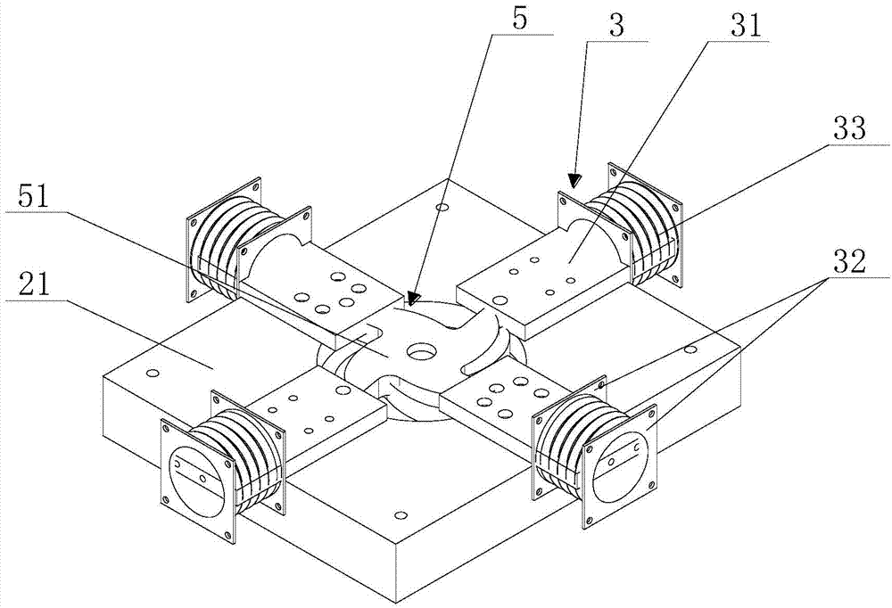
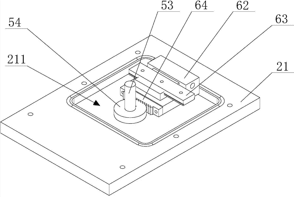
[0040] A self-centering fixture provided by the present invention such as figure 1 ,Please refer to Figure 1 to Figure 5 , Figure 7 , Figure 8 , as shown in the figure, includes a base 1 , a main body 2 , at least three actuator components 3 , a driving component 5 , and a clamping component 7 . The base 1 is fixed on the processing table of the machine tool through a fixed structure, the main body 2 is arranged on the base 1, and a storage cavity is formed inside it, and a plurality of execution components 3 and driving components 5 are arranged in the storage cavity, clamping The component 7 is connected to the execution component 3 . Driven by the execution part 5, a plurality of execution parts 3 uniformly distributed in the main body 2 at equal angles can reciprocate synchronously along the direction connecting the center and the edge of the main body 2. Through the reciprocating motion of the execution part 3, the The clamping part 7 automatically centers and clam...

Embodiment 2

[0054] Another self-centering fixture provided by Embodiment 2 of the present invention is as Image 6 , Figure 9 , Figure 10 As shown, its overall structure is the same as that of the first embodiment, except that the cam in the second embodiment uses a guide groove cam 52 .

[0055] Please refer to Figure 9 , Figure 10 , the main body of the guide groove cam 52 is a circular structure, on the main body of the guide groove cam 52 corresponding to each slide block 31 is provided with a guide groove 52c, the guide groove 52c is spirally arranged along the center of the guide groove cam 52 and the direction connecting the edges, One end of the guide groove 52c close to the edge of the guide groove cam 52 forms an outer pushing portion 52a, and the other end thereof forms an inner return portion 52b. The center of the guide cam 52 is also provided with a connecting hole 52d connected with the rotating shaft 53 , and the rotating shaft 53 drives the guide cam 52 to rotate ...


PUM


Abstract

The invention provides a self-centering clamp. The self-centering clamp is used for positioning and clamping workpieces to be machined and comprises a base, a main body, at least three executing components and a driving component, wherein the main body is arranged on the base; the executing components are horizontally arranged in the main body at equal angles and can move in a reciprocating manner in the direction of a connecting line between the center of the main body and the edge of the main body; the driving component is used for driving the executing components to move in a reciprocating manner; each executing component is provided with a clamping component; the clamping components can be used for clamping the workpieces when the executing components move towards the center of the main body; each executing component comprises at least three sliders; the driving component comprises a cam and a rotating shaft; the cam is provided with an outward pushing portion and an inward returning portion; the rotating shaft is connected with the cam; the cam can be driven to rotate by the rotating shaft; and the cam guides the sliders to move in a reciprocating manner, so that a workpiece clamping state and a workpiece unloading state of the clamping portions can be changed over. The existing complex working procedures of manually centering the workpieces and adjusting clamps during clamping are omitted.

Description

technical field [0001] The invention relates to a machine tool fixture, in particular to a self-centering fixture. Background technique [0002] General-purpose fixtures mainly include vices, three-jaw chucks, four-jaw chucks, etc., which are mainly used for clamping and fixing rotating workpieces (or blanks) with regular shapes, but for workpieces that are not rotating or have complex shapes The workpiece (or rough blank) obviously cannot be properly clamped with the above three fixtures. However, unreasonable clamping often reduces the machining accuracy, damages the workpiece (or blank), and eventually causes a large error in the size of the workpiece. Sometimes even the processing process is full of danger due to insufficient clamping force. Not only that, the general fixture often needs to be disassembled repeatedly to clamp regular workpieces (or blanks) of different shapes, and the process is cumbersome. [0003] Chinese patent CN103706824 discloses a four-jaw sing...

Claims


Application Information

Patent Timeline
Patent Type & Authority Applications(China)
IPC IPC(8): B23Q3/00
CPCB23Q3/06B23Q3/08B23Q2703/04
Inventor 郭创马春风
Owner 深圳市速优精密机械有限公司
Why Eureka
Try Eureka