Flexible circuit board drilling method

A flexible circuit board and drilling method technology, applied in metal processing and other directions, can solve the problems of increasing processes, increasing material and labor costs, increasing the mechanical force on the edge of the hole, etc., to reduce the probability of the drill tip breaking, The effect of reducing labor and material costs and improving the pass rate

Inactive Publication Date: 2015-01-07
宁波赛特信息科技发展有限公司
View PDF7 Cites 2 Cited by
  • Summary
  • Abstract
  • Description
  • Claims
  • Application Information

AI Technical Summary

Problems solved by technology

When the hole distance and hole diameter are small, the mechanical force on the edge of the hole will increase, the drill speed will increase, and the drilling speed will increase, resulting in a large amount of heat generated by friction, and the temperature of the drill will increase accordingly. Burn the cover film, or even burn off the cover film connecting bridg

Method used


Image

  • Flexible circuit board drilling method

Examples


Embodiment Construction

[0013] The present invention will be described in further detail below in conjunction with the accompanying drawings and specific embodiments.

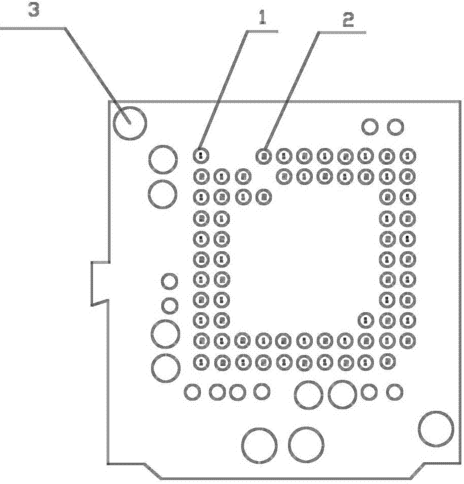
[0014] Such as figure 1 Shown, a kind of flexible printed circuit board drilling method, its steps are:

[0015] (1) The first drill bit and the second drill bit are arranged side by side and independently on the drilling machine;

[0016] (2) Use the first drill bit to drill the first group of holes in sequence on the circuit board, and then use the second drill bit to drill the second group of holes in sequence on the circuit board. The group of boreholes and the second group of boreholes are respectively distributed at intervals in the up-down and left-right directions.

[0017] In addition, the positioning hole 3 is formed by drilling the circuit board before step (2). Position the circuit board through the positioning hole corresponding to the positioning on the drilling machine, which is convenient for the next step, and accu...


PUM


Abstract

The invention relates to a flexible circuit board drilling method which includes the steps of firstly, parallelly and independently disposing a first drill bit and a second drill bit on a drilling machine; secondly, using the first drill bit to sequentially drill a first group of holes in a circuit board, and using the second drill bit to sequentially drill a second group of holes in the circuit board, wherein the first group of holes and the second group of holes are distributed in the up-down and left-right directions at intervals. The method has the advantages that a cover film is directly used for drilling by improving the drilling procedures, an ink printing procedure is not needed, product yield is increased, manpower and material cost is reduced correspondingly, delivery time is reduced, and probability of drill bit breaking is reduced.

Description

technical field [0001] The invention relates to a production process of a flexible circuit board, in particular to a drilling method. Background technique [0002] During the manufacturing process of flexible circuit boards, through holes of different sizes need to be drilled on the surface of the substrate to pave the way for connecting the conductive properties of the two sides of the circuit, or for identification and positioning in subsequent processes. With the development of technology, the diameter of the drilled hole has been reduced to 1.0mm, and the hole-to-hole spacing has been reduced to 1.03mm. The mechanical force and heat generated during drilling have put forward higher requirements for the drilling process. When the hole distance and hole diameter are small, the mechanical force on the edge of the hole will increase, the drill speed will increase, and the drilling speed will increase, resulting in a large amount of heat generated by friction, and the tempera...

Claims


Application Information

Patent Timeline
IPC IPC(8): B26F1/16
CPCB26F1/16
Inventor 岑冲平
Owner 宁波赛特信息科技发展有限公司
Why Eureka
Try Eureka