Track locomotive braking clamp unit brake block gap adjuster

A technology of vehicle brake caliper and gap adjuster, which is applied in the direction of brake wear compensation mechanism, railway braking system, railway car body parts, etc. problems, to achieve the effect of simple structure, small footprint, and high modularity

Active Publication Date: 2015-01-07
CRRC QINGDAO SIFANG ROLLING STOCK RES INST +1
View PDF5 Cites 9 Cited by
  • Summary
  • Abstract
  • Description
  • Claims
  • Application Information

AI Technical Summary

Problems solved by technology

The brake shoe clearance adjustment device is set on the brake screw, the maintenance and replacement process is cumbersome, and the brake output of the brake cylinder is easily affected

Method used


Image

  • Track locomotive braking clamp unit brake block gap adjuster
  • Track locomotive braking clamp unit brake block gap adjuster
  • Track locomotive braking clamp unit brake block gap adjuster

Examples


Embodiment 1

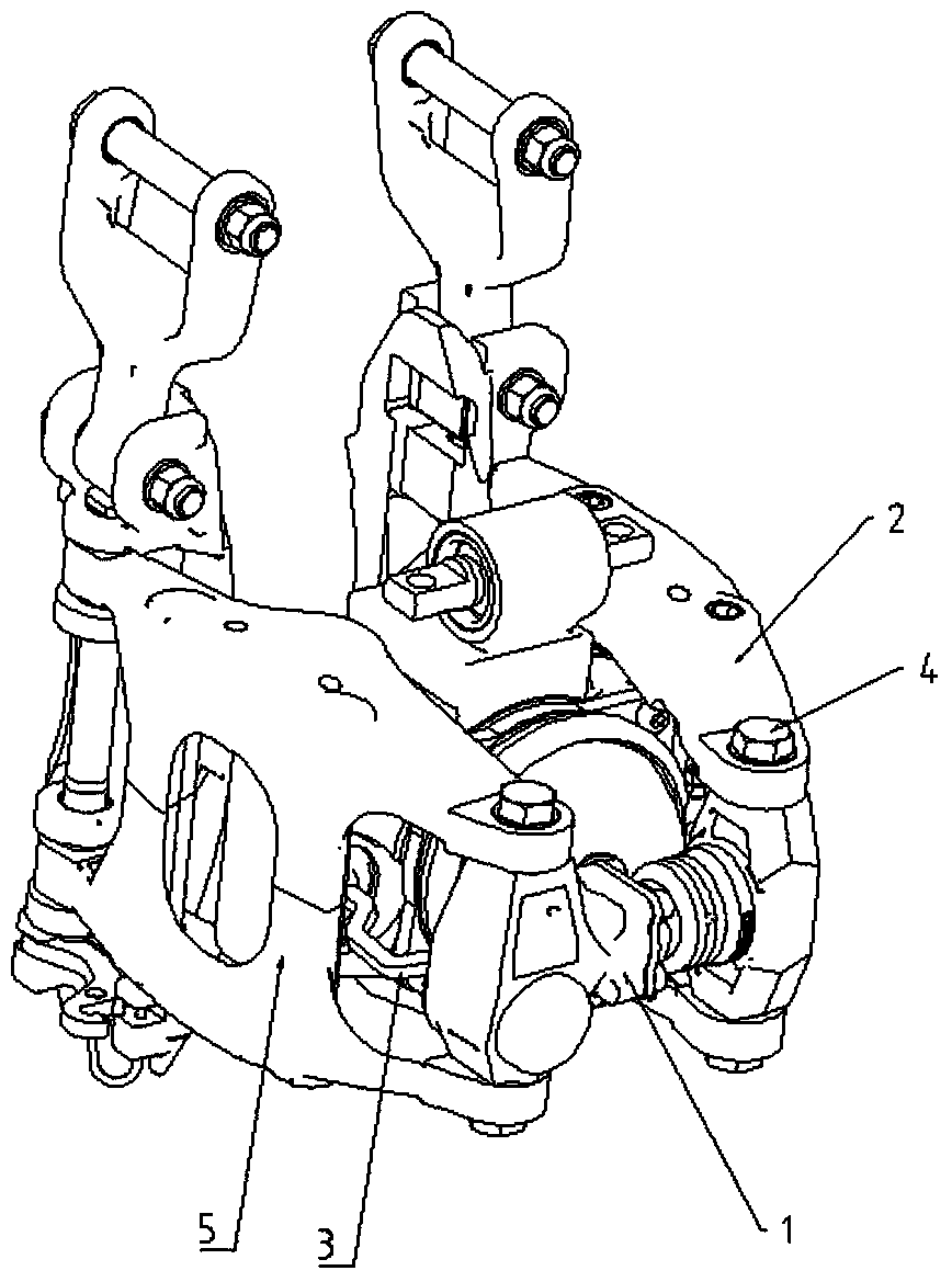
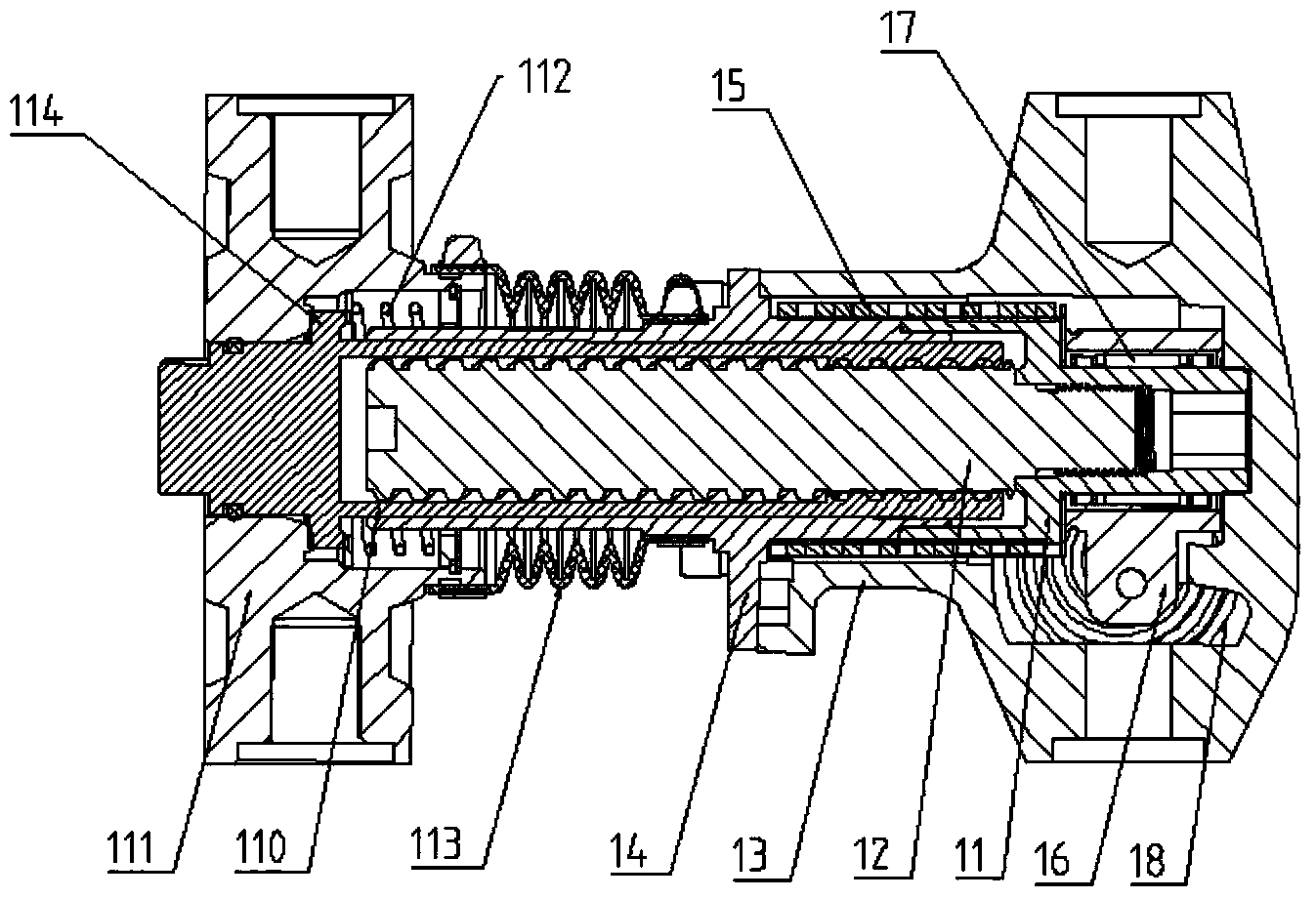
[0018] The rail locomotive vehicle brake caliper unit brake pad gap adjuster 1 of the present embodiment comprises a left box body 13 and a right box body 111, and the upper and lower ends of the left box body 13 and the right box body 111 are respectively provided with connecting ends, and the left box body 13 and the right box body 111 are respectively provided with connecting ends. The box 13 and the right box 111 are respectively hinged with the left brake caliper arm 5 and the right brake caliper arm 2 of the brake caliper unit through the pin 4, and the left box 13 is provided with a one-way torsion spring friction Clutch, friction shaft 11 and lead screw 12 are fixedly connected by left-handed thread to form a driving shaft; connecting pipe 14 is fastened on the left box body 13, and friction torsion spring 15 is set to hold the connecting pipe 14 and friction shaft 11 tightly; connecting pipe 14 and The outer diameter of the part where the friction shaft 11 is held tigh...

Embodiment 2

[0020] The rail locomotive vehicle brake caliper unit brake pad gap adjuster of this embodiment is the same as Embodiment 1 except for the following differences:

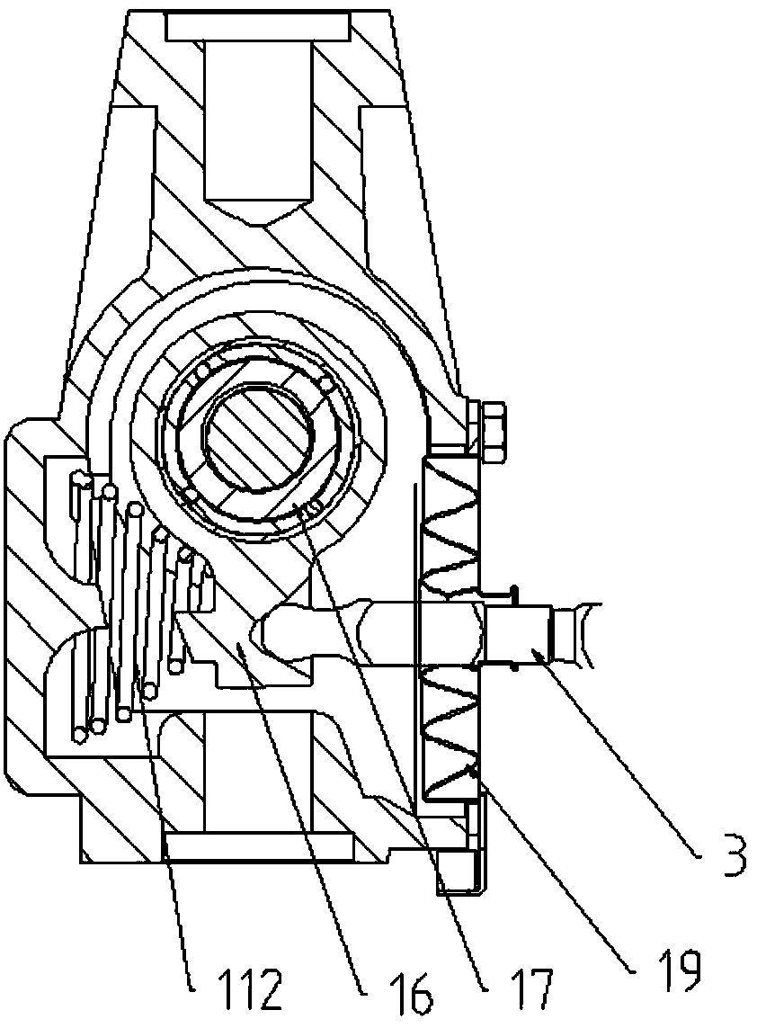
[0021] A corrugated disk-type rubber dustproof cover 19 is provided at the contact opening of the left box body 13 and the push rod 3 . A flexible bellows-type rubber dustproof cover 113 is provided on the outside of the joint between the left box body 13 and the right box body 111, and has a breathing hole.

[0022] During use, the connecting ends of the left box body 13 and the right box body 111 of the rail vehicle brake caliper unit brake pad clearance adjuster 1 are respectively connected with the left brake caliper arm 5 and the right brake caliper of the brake caliper unit. The pliers arm 2 is hinged through the pin shaft 4, and the rotating arm sleeve 16 and the push rod 3 are hinged through a spherical pair.

[0023] When there is a situation or trend that the gap between the brake pads is too large due to...


PUM


Abstract

The invention belongs to the technical field of brake gap adjusters and relates to a track locomotive braking clamp unit brake block gap adjuster. The track locomotive braking clamp unit brake block gap adjuster comprises a left box and a right box; a one-way torsional spring type friction clutch is arranged inside the left box; a frictional shaft is fixedly connected with a screw through threads; a connecting pipe is fastened on the left box; a frictional torsional spring tightly holds the connecting pipe and the frictional shaft always; a rotary arm sleeve is arranged on a driving shaft; a one-way bearing is arranged between the rotary arm sleeve and the frictional shaft; a bevel gear clutch is arranged inside the right box; a bevel gear pair is arranged between a limit gear of a manual adjustment nut and the right box; a compression spring is arranged on the right box and the limit gear; the manual adjustment nut and the right box are in engaged states always; the manual adjustment nut sleeves the external side of the screw and is in threaded connection with the screw. The track locomotive braking clamp unit brake block gap adjuster is reasonable in design, simple in structure, high in adjustment efficiency, small in occupied space, installed outside a brake cylinder and hinged to a braking clamp arm during utilization and convenient to assemble, disassemble and maintain and accurately achieves functions of self-compensating and manual adjusting of brake block gaps.

Description

technical field [0001] The invention belongs to the technical field of brake clearance adjusters, and in particular relates to a component module of a brake caliper unit of a railway locomotive, especially a module placed outside the brake caliper unit and used for compensation and adjustment of brake pad wear clearance Brake slack adjuster. Background technique [0002] The brake pads and brake discs installed on the brake caliper unit will become thinner after wearing for a period of time. Generally, the stroke of the brake cylinder of the brake caliper unit of rail vehicles is set to be constant, so it is necessary to set it for it. The brake pad gap adjuster is used to compensate and adjust the brake pad wear gap to ensure the stability of the brake pad pressure. The existing brake pad clearance adjusters generally have a relatively complex structure, low adjustment efficiency, and a low degree of modularization. [0003] Chinese patent CN 102039912 A discloses a brake...

Claims


Application Information

Patent Timeline
Patent Type & Authority Applications(China)
IPC IPC(8): B61H15/00
CPCB61H15/0085
Inventor 王震覃立伟黄建松张方亮张昕
Owner CRRC QINGDAO SIFANG ROLLING STOCK RES INST
Why Eureka
Try Eureka