Rotary lifting device
A technology of lifting device and rotating shaft, which is applied in the field of machinery, can solve the problems of strong mechanical shock and low production efficiency, and achieve the effects of high automation, high production efficiency and reasonable design
- Summary
- Abstract
- Description
- Claims
- Application Information
AI Technical Summary
Problems solved by technology
Method used
Image

Examples
Embodiment 1
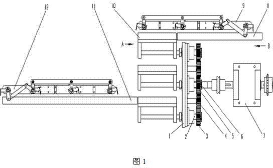
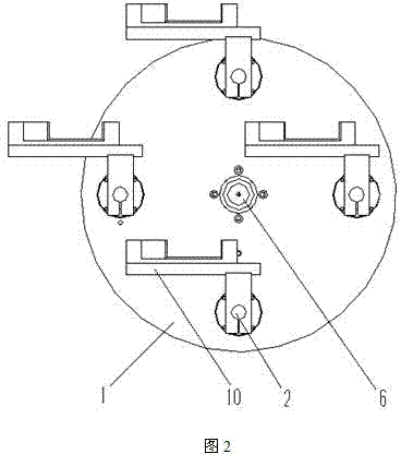
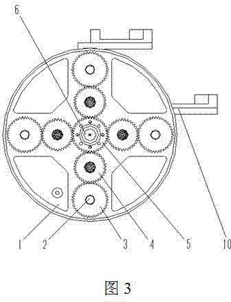
[0016] Such as figure 1 , figure 2 with image 3 As shown, the rotary lifting device of the present invention includes a frame, a planetary gear mechanism and an object table 10, the planetary gear mechanism is installed on the frame, and the object table 10 is connected to the planetary gear mechanism. The planetary gear mechanism includes a central shaft 6 , a turntable 1 , a sun gear 5 , an intermediate gear 4 , a planetary gear 3 and a rotating shaft 2 . The central shaft 6 is installed on the bearing of the frame, the sun gear 5 is fixed on the central shaft 6, the turntable 1 is equipped with a central bearing and a planetary bearing, and a support shaft is fixed on one side thereof, and the support shaft An intermediate wheel 4 is installed on the top, the turntable 1 is installed on the central shaft 6 through a central bearing, the rotating shaft 2 is installed on the planetary bearing on the turntable 1, and a planetary wheel 3 is fixed at one end. The sun gear 5...
Embodiment 2
[0018] This embodiment is basically similar to Embodiment 1, the difference is that this embodiment also has a first push-pull rod 9 (or manipulator) installed on the first support frame 8, and is facing the object table 10 with the turntable 1 to the maximum position. In the lower position, the second push-pull rod 11 (or manipulator) is installed on the second support frame 12, and rotates to the uppermost position with the turntable 1 facing the object table 10. Through the first push-pull rod 9 or the second push-pull rod 11, when the object table 10 is located at the lowermost position or the uppermost position, the object can be picked and placed while the table surface of the object table 10 remains in the initial horizontal state.
Embodiment 3
[0020] This embodiment is basically similar to Embodiment 1, the difference is that at least two or four sets of rotating shafts 2 and object tables 10 are evenly distributed on the turntable 1 of this embodiment. The present invention connects the intermittent mechanism at the input end of the central shaft 6, and the present embodiment adopts the cam splitter 7. In this embodiment, the first push-pull rod 9 may be installed facing the object table 10 and rotated to the leftmost position with the turntable 1, and the second push-pull rod 11 may be installed directly opposite the object table 10 and rotated to the far right with the turntable 1. square location. The rotary lifting device of this embodiment, through the action of the cam divider 7, meets the demand for intermittent object pick-and-place, or realizes that the object table 10 stops at any position (angle) for pick-and-place objects. Through multiple sets of object tables 10, objects can be picked and placed in a...
PUM
 Abstract
Description
Claims
Application Information