Sleeve combination tool type platform of cantilever scaffold and operating method thereof

A technology of cantilevered scaffolding and combined tools, which is applied in the field of cantilevered scaffolding, can solve the problems of low turnover, low efficiency, and inability to adjust the vertical distance of vertical poles, so as to save the amount of use, improve the installation efficiency, and avoid the effect of cross-arrangement.

Active Publication Date: 2015-01-07
江苏邗建集团有限公司
View PDF7 Cites 9 Cited by
  • Summary
  • Abstract
  • Description
  • Claims
  • Application Information

AI Technical Summary

Problems solved by technology

[0002] The currently used cantilevered scaffolding system for building construction is composed of I-beams, steel pipe fasteners, bamboo fences, protective nets, etc. The degree of instrumentation is low, the installation efficiency is low, the risk is relatively large, and there are the following disadvantages:
[0003] 1. The positioning bolts are welded on the I-beam, so that the longitudinal distance of the vertical pole becomes non-adjustable. When adjustment is required, it is often necessary to cut off and then weld
[0004] 2. There are many I-beam layouts at the corners of the floors, and the cross layout leads to different heights of scaffolding poles
[0005] 3. Since the vertical closure can only be realized after the scaffolding is completed, on the one hand, the upper construction personnel are more dangerous when operating, on the other hand, it also buryes safety hazards for the production and construction of the bottom personnel
[0006] 4. Bamboo fences, scaffolding boards and other closed protective materials have poor sealing effect, large loss, low turnover times, and are not clean and beautiful

Method used


Image

  • Sleeve combination tool type platform of cantilever scaffold and operating method thereof
  • Sleeve combination tool type platform of cantilever scaffold and operating method thereof
  • Sleeve combination tool type platform of cantilever scaffold and operating method thereof

Examples


Embodiment Construction

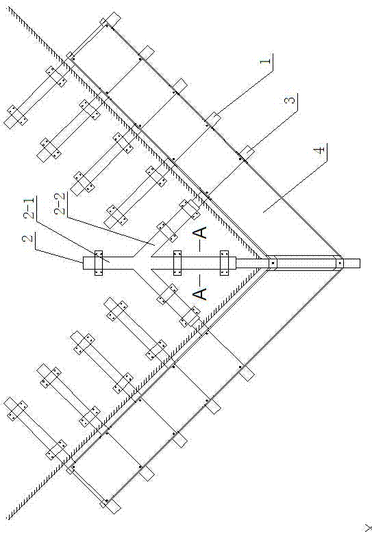
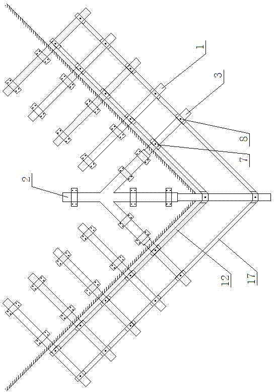
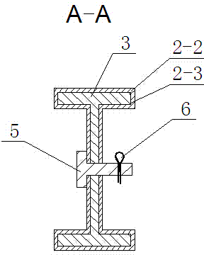
[0033] like figure 1 As shown in -10, the present invention mainly includes several intermediate cantilever I-beams 1 fixed on the floor and sleeve tools 2 fixed at four corners of the floor. A fixed trunk 2-1 and three I-beam sleeves 2-2 on the plane. The three I-beam sleeves 2-2 are fan-shaped and integrally arranged at one end of the fixed trunk 2-1. An I-shaped inner cavity 2-3 is respectively arranged in the steel sleeve 2-2, and a corner cantilevered I-beam 3 is respectively inserted in each I-beam sleeve 2-2, and each corner cantilevered I-beam 3 They are respectively connected with the corresponding I-beam sleeves 2 - 2 through the first plug bolts 5 and the first split pins 6 .

[0034] A rectangular hollow inner sleeve 7 and a rectangular hollow outer sleeve 8 are sleeved on each middle cantilevered I-beam 3 and each corner cantilevered I-beam 1 and fixed by fastening bolts 9 respectively. The upper end of each rectangular hollow inner sleeve 7 is respectively fixe...


PUM


Abstract

The invention provides a sleeve combination tool type platform of a cantilever scaffold and an operating method thereof and relates to the field of constructional engineering cantilever scaffolds. The sleeve combination tool type platform comprises a plurality of pieces of middle cantilever I-steel and four sleeve tools, wherein corner cantilever I-steel is inserted into the four sleeve tools respectively. Each middle cantilever I-steel and each corner cantilever I-steel are sleeved with an inner sleeve and an outer sleeve respectively. A first bolt is fixedly connected at the upper end of each inner sleeve, first shelving platforms are fixedly connected to two sides of each inner sleeve, and first channel steel is arranged between two adjacent inner sleeves. A second bolt is fixedly connected to the upper end of each outer sleeve, second shelving platforms are fixedly connected to two sides of each outer sleeve, and second channel steel is arranged between two adjacent inner sleeves. The same steel plate is arranged above each first channel steel and the corresponding second channel steel. The sleeve combination tool type platform is high in instrumentalization degree and can greatly improve installing efficiency, save materials and labor cost and strengthen operating safety.

Description

technical field [0001] The present invention relates to the field of cantilevered scaffolding for construction projects. Background technique [0002] The currently used cantilever scaffolding systems for building construction are composed of I-beams, steel pipe fasteners, bamboo fences, protective nets, etc. The degree of tooling is low, the installation efficiency is low, the danger is high, and there are the following shortcomings: [0003] 1. The positioning bolts are welded on the I-beam, so that the vertical distance of the vertical rod becomes unadjustable. When adjustment is required, it is often necessary to cut off and then weld. [0004] 2. There are many I-beam arrangements at the corners of the floors, and the cross arrangement leads to different heights of scaffolding poles. [0005] 3. Since the vertical closure can only be achieved after the scaffolding is completed, on the one hand, the upper construction personnel are more dangerous when operating, and on ...

Claims


Application Information

Patent Timeline
Patent Type & Authority Applications(China)
IPC IPC(8): E04G3/18E04G5/04
Inventor 张学军徐永海黄伟陈有威
Owner 江苏邗建集团有限公司
Why Eureka
Try Eureka