A bag lock structure

A luggage lock and luggage technology, which is applied in building locks, building structures, buildings, etc., can solve the problems of single structural design, complex transmission structure, and inconvenient switching of luggage locks, and achieve convenient structural layout, good hand feeling, and beautiful appearance Effect

Active Publication Date: 2016-09-07
SHANGHAI DAMAO LUGGAGE
View PDF6 Cites 0 Cited by
  • Summary
  • Abstract
  • Description
  • Claims
  • Application Information

AI Technical Summary

Problems solved by technology

[0004] The technical problem to be solved in the present invention is: the existing luggage locks can only be installed on the side of the luggage due to their own structural limitations, resulting in a single structural design of the luggage locks; Complicated, resulting in high cost, high failure rate, and inconvenient opening and closing; the lock is installed on the side of the luggage, and the luggage often collides during the consignment, which is easy to cause damage to the lock body

Method used


Image

  • A bag lock structure
  • A bag lock structure
  • A bag lock structure

Examples


Embodiment Construction

[0031] The present invention will be further described below in conjunction with specific examples.

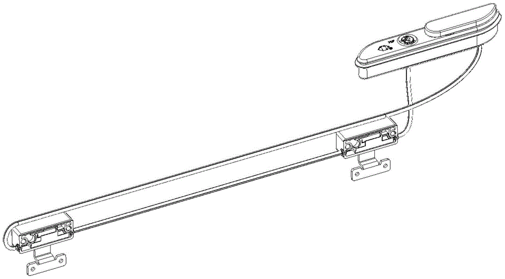
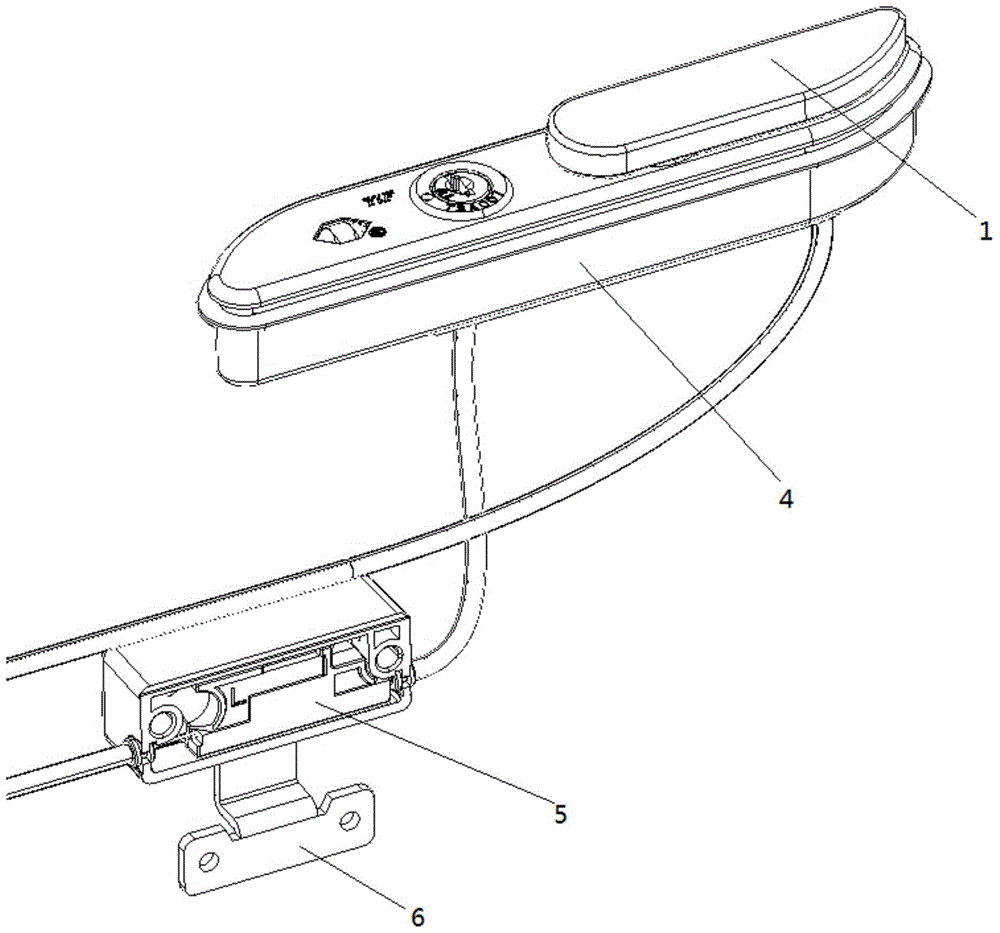
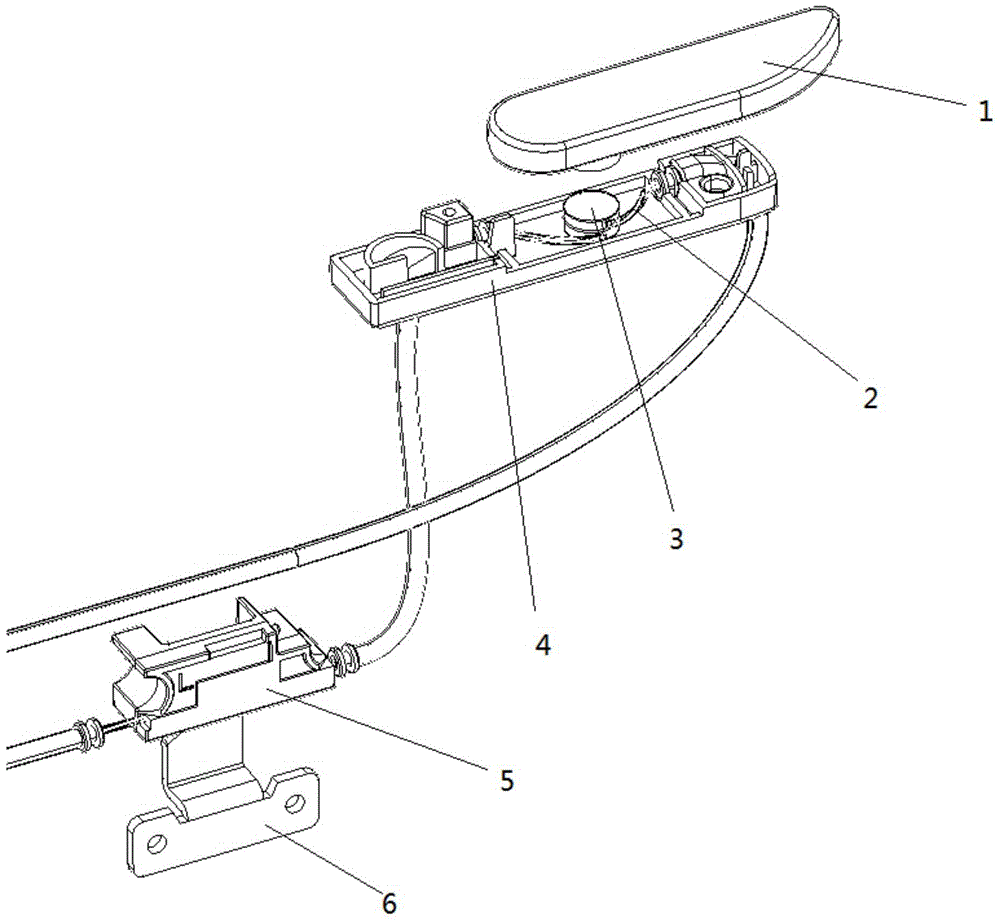
[0032] see Figure 1-10 , a luggage lock structure, comprising a lock body 4, a wrench 1, a lock rope 2, a rotating shaft 3, a lock head 5, and a lock hook 6; The two ends of the rotating shaft 3 and the lock rope 2 are connected in the same direction in the radial direction of the rotating shaft. The wrench 1 is connected to the rotating shaft 3 to drive the rotating shaft 3 to rotate; the locking rope 2 is connected to the lock head 5, and the lock head 5 is connected to the The fastening surface of the lock hook 6 is parallel to the lock rope 2 .

[0033] see Figure 4 , two parallel guide grooves 301 are provided on the circumference of the rotating shaft 3, which correspond to the two ends of the lock rope 2 respectively, and guide the lock rope 2 to prevent the lock rope 2 from moving up and down inside the lock body.

[0034] see Figure 1-3 , also includes a lock c...


PUM


Abstract

The invention relates to a luggage lock structure, which is characterized in that it comprises a lock body, a wrench (1), a lock rope (2), a rotating shaft (3), a lock head (5), and a locking hook (6); the rotating shaft is arranged on In the lock body, the sides of the rotating shaft are respectively connected with the two ends of the lock rope, and the two connecting parts of the rotating shaft and the lock rope are located in the same radial direction of the rotating shaft. The wrench is connected with the rotating shaft to drive the rotating shaft to rotate; The fastening surface of the head and the shackle is parallel to the lock cord. When the wrench drives the rotating shaft to rotate, since the two ends of the lock rope are fixed at the same radial position on the side of the rotating shaft, the rotating shaft can drive the lock rope to move back and forth slightly, and the lock rope can drive the lock head on it to move back and forth slightly , so as to realize the fastening and separation between the lock head and the shackle. The lock rope has a very high degree of freedom and can be converted in any direction, which is convenient for the position selection of the lock set on the box and improves the degree of freedom.

Description

technical field [0001] The invention relates to a lock structure, specifically a luggage lock structure, belonging to the technical field of locks. Background technique [0002] Due to the limitation of the structure of the luggage itself, the existing luggage locks are generally installed on the side of the luggage. The plane where people open and close the action and the plane where the lock head and the lock buckle are engaged and separated can generally only be designed on the same plane. In the plane, the structure design of the luggage lock is single; while the transmission structure of the characteristic lock is generally more complicated, resulting in higher cost, high failure rate, and inconvenient switch. [0003] At the same time, the lock is installed on the side of the luggage, and the luggage often collides during the consignment, which may easily cause damage to the lock body. Contents of the invention [0004] The technical problem to be solved in the pres...

Claims


Application Information

Patent Timeline
Patent Type & Authority Patents(China)
IPC IPC(8): E05B65/52
Inventor 柯慧子
Owner SHANGHAI DAMAO LUGGAGE
Why Eureka
Try Eureka