
Air filter for vehicles

An air filter and vehicle technology, applied in the field of vehicles, can solve the problems of reducing the service life of the engine, reducing the intake efficiency of the engine, carbon deposition in the cylinder, etc., and achieving the effects of prolonging the service life, reducing pollution and sufficient combustion

Active Publication Date: 2015-01-07
GREAT WALL MOTOR CO LTD
View PDF5 Cites 4 Cited by
  • Summary
  • Abstract
  • Description
  • Claims
  • Application Information

AI Technical Summary

Problems solved by technology

[0002] In order to discharge the oil-air mixture in the crankshaft ventilation box, reduce the pressure in the crankshaft ventilation box and reduce the damage of the oil-air mixture to the oil in the crankshaft ventilation box, it is necessary to implement crankshaft ventilation box ventilation. In the related art, the crankshaft ventilation box and air filter The exhaust side shell of the cleaner is connected, and the oil-air mixture is directly discharged into the exhaust side shell, which will destroy the flow field formed by the air entering the exhaust side shell through the filter element, resulting in increased air intake resistance. Reduced intake efficiency of the engine directly affects the fuel economy and power of the engine
[0003] In addition, the oil-air mixture enters the air filter, which will pollute the flow sensor (or temperature sensor) on the air filter
The oil-air mixture enters the engine with fresh air and burns again, which may easily cause insufficient combustion of combustible gas in the engine, carbon deposits and scratches in the cylinder, and reduce the service life of the engine

Method used


Image

  • Air filter for vehicles
  • Air filter for vehicles
  • Air filter for vehicles

Examples


Embodiment Construction

[0028] Embodiments of the present invention are described in detail below, examples of which are shown in the drawings, wherein the same or similar reference numerals designate the same or similar elements or elements having the same or similar functions throughout. The embodiments described below by referring to the figures are exemplary and are intended to explain the present invention and should not be construed as limiting the present invention.

[0029] It should be noted that, in the case of no conflict, the embodiments of the present invention and the features in the embodiments can be combined with each other.

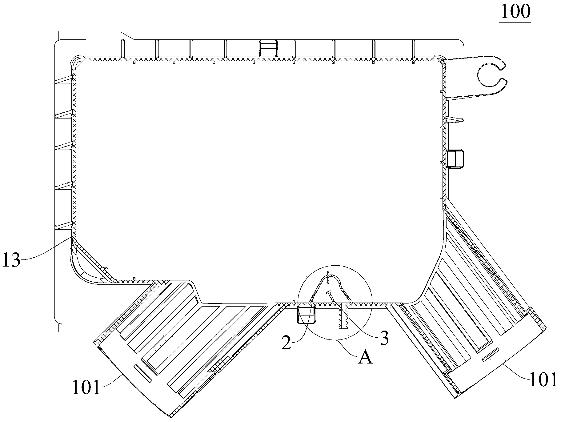
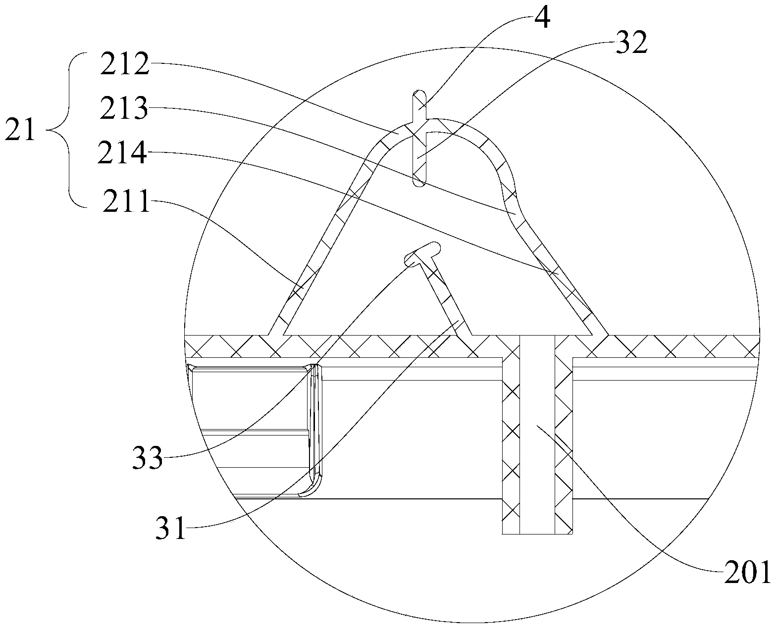
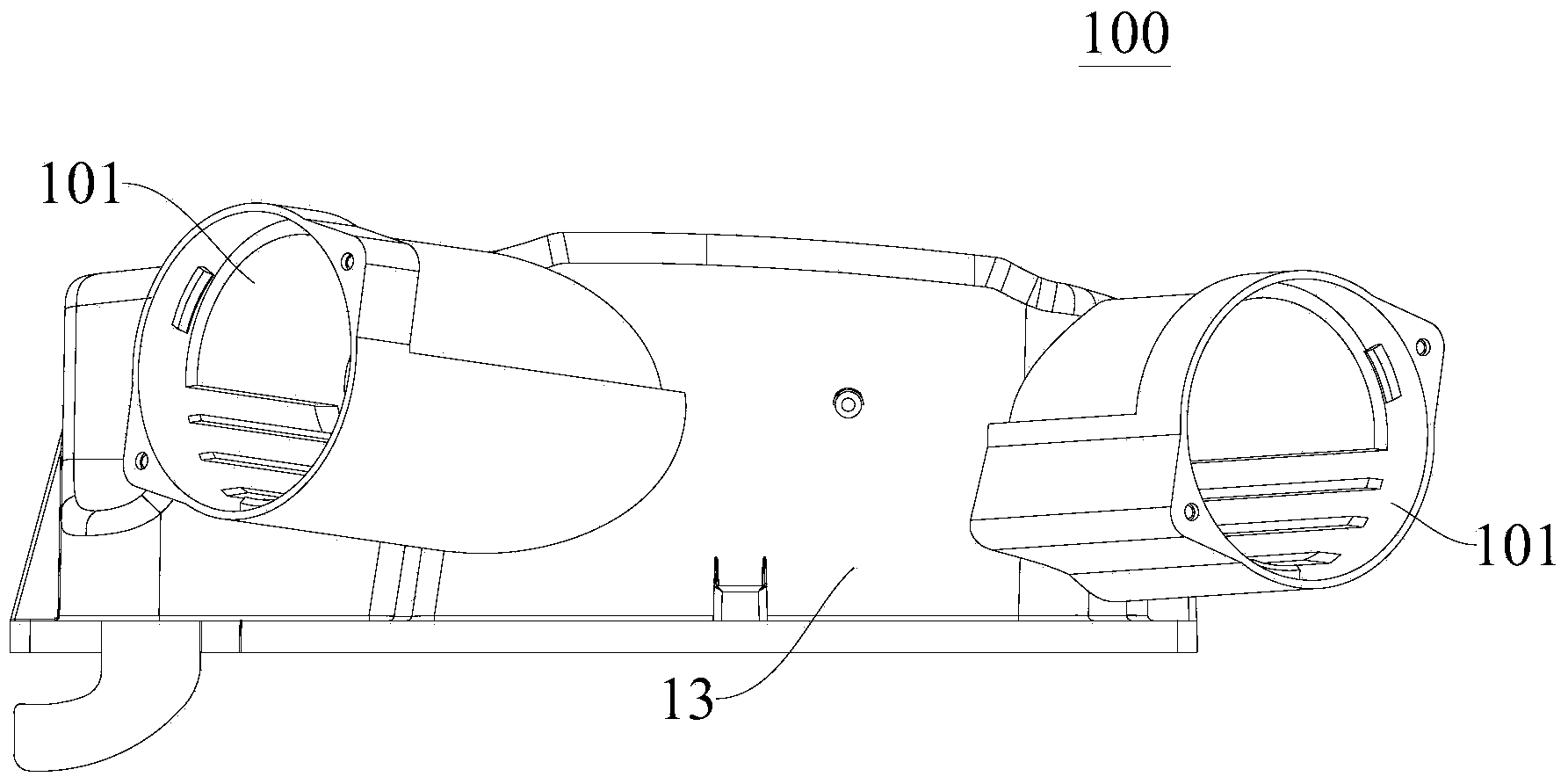
[0030] Refer below Figure 1-Figure 7 The air cleaner 100 for a vehicle according to an embodiment of the present invention will be described in detail.

[0031] The air cleaner 100 for a vehicle according to an embodiment of the present invention may include: a casing, an isolation structure 2 and a flow blocking structure 3 .

[0032] Among them, such as ...


PUM


Abstract

The invention discloses an air filter for vehicles. The air filter comprises a casing, a separation structure and a flow blocking structure. A filter element is arranged in the casing and separates the casing into an air inlet side casing portion and an air exhausting side casing portion, the air inlet side casing portion is provided with an air inlet, and the air exhausting side casing portion is provided with an air exhausting port. The separation structure is arranged on the side wall of the air exhausting side casing portion and located in the air exhausting side casing portion. The separation structure is provided with an oil gas connector suitable to be connected with a crankshaft ventilation box, and one side of the separation structure facing the filter element is opened. The flow blocking structure is arranged in the separation structure so as to lead oil gas mixtures entering the separation structure to generate eddy currents. According to the air filter for the vehicles, the oil gas mixtures with a certain pressure in the crankshaft ventilation box is prevented from damaging the gas current flow field in the air exhausting side casing portion, pollution of the oil gas mixtures on a sensor disposed in the air filter is reduced, the phenomenon of car deposition and scratching in a cylinder is changed, and the service life of the engine is prolonged.

Description

technical field [0001] The invention relates to the technical field of vehicles, in particular to an air filter for vehicles. Background technique [0002] In order to discharge the oil-air mixture in the crankshaft ventilation box, reduce the pressure in the crankshaft ventilation box and reduce the damage of the oil-air mixture to the oil in the crankshaft ventilation box, it is necessary to implement crankshaft ventilation box ventilation. In the related art, the crankshaft ventilation box and air filter The exhaust side shell of the cleaner is connected, and the oil-air mixture is directly discharged into the exhaust side shell, which will destroy the flow field formed by the air entering the exhaust side shell through the filter element, resulting in increased air intake resistance. The reduction of engine air intake efficiency directly affects the fuel economy and power of the engine. [0003] In addition, the oil-air mixture enters the air filter, which will contamin...

Claims


Application Information

Patent Timeline
Patent Type & Authority Applications(China)
IPC IPC(8): F01M13/04
CPCF01M11/08F02M35/024
Inventor 韩严胜吴春明梁志涛郑锐利贾晓伟
Owner GREAT WALL MOTOR CO LTD
Learn More