Water mixing device

A technology of water mixing and water end, which is applied in the direction of valve device, valve operation/release device, valve details, etc. It can solve the problems of inconvenient installation and use on site, increase of overall length and volume, increase of sealing points, etc., and reduce pipe fittings Amount and volume, easy installation and maintenance, reduce the effect of connection

Active Publication Date: 2015-01-07
RIFENG ENTERPRISE FOSHAN CO LTD +2
View PDF6 Cites 6 Cited by
  • Summary
  • Abstract
  • Description
  • Claims
  • Application Information

AI Technical Summary

Problems solved by technology

[0002] A common floor heating device includes a water separator, a water collector, and a water mixing device, wherein the water mixing device includes a thermostatic mixing valve and a circulation pump, such as figure 1 As shown in , the valve body 1 of an ordinary thermostatic mixing valve is a three-way structure, which includes a return water port 2 connected to the water collector, a water inlet port 3 connected to the external hot water, and a circulating pump 6 The connected mixing water end 4, the adjustment handle 5 is located on the other side opposite to the mixing water end 4, the return water end 2, the water inlet end 3, the mixing water end 4 and the adjustment handle 5 are on the same horizontal plane, see figure 2 , when the valve body 1 of the thermostatic mixing water valve is used in floor heating mixed water, it is necessary to add a water inlet elbow 7 to connect the external hot water, and add a return water tee 8 to connect the water collector and the external return water, There are more corresponding joints and more sealing points, which are prone to hidden dangers of leakage
Such a water mixing device needs to add more connecting joints and pipe fittings, the overall length and volume increase accordingly, and it is inconvenient to install and use on site

Method used


Image

  • Water mixing device
  • Water mixing device
  • Water mixing device

Examples


Embodiment

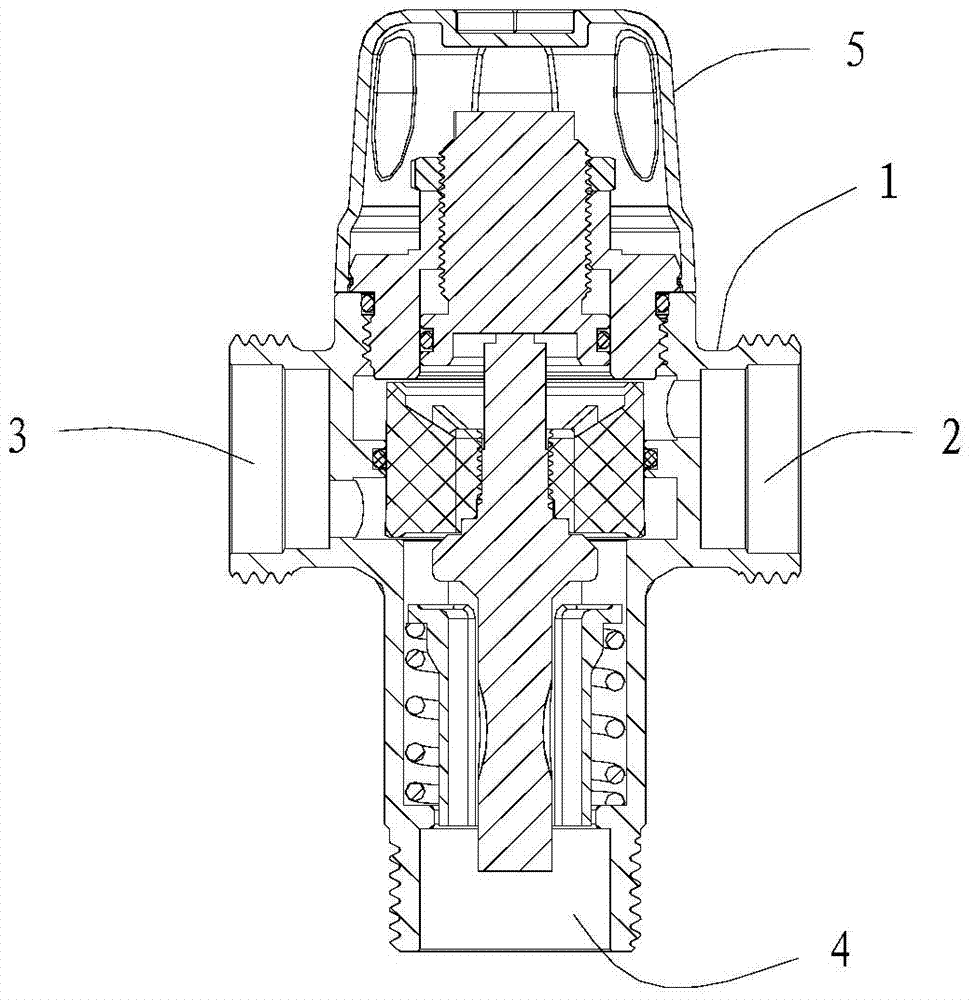
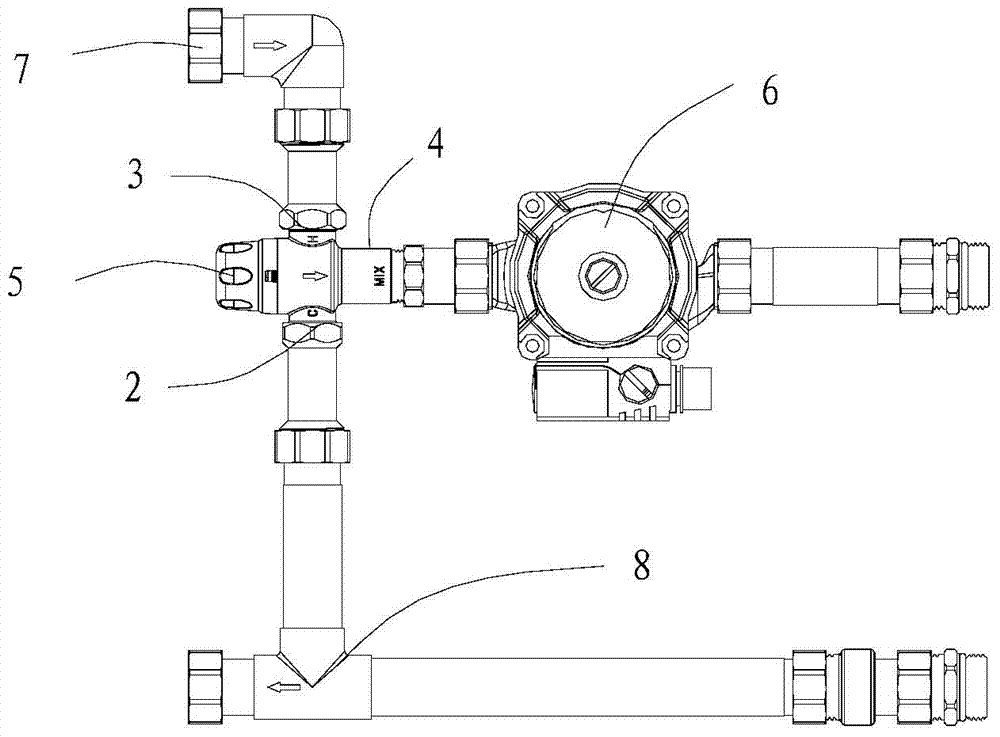
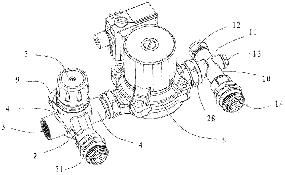
[0029] refer to Figure 3-12 , a water mixing device, including a thermostatic mixing valve body 1 with an adjustment handle 5, a return water end 2, an inlet water end 3, a mixing water end 4, a second water return end 9, and a circulating pump 6, wherein the second The return water end 9 is located on the same plane as the return water end 2, the water inlet end 3 and the mixing water end 4. The adjustment handle 5 is vertically arranged on the valve body 1, and the outlet of the circulation pump 6 is provided with a water diversion cross 10, and the water diversion The four-way 10 is provided with a first port 11 connected to the outlet of the circulation pump 6 , a second port 12 connected to the bypass interface, a third port 13 connected to the exhaust valve and a fourth port 14 connected to the inlet of the water separator.

[0030] The valve body 1 of the thermostatic water mixing valve is a four-way structure, and its four ports are located on the same plane, which ar...


PUM


Abstract

The invention discloses a water mixing device. The water mixing device comprises a constant-temperature water mixing valve body and a circulating pump, wherein the constant-temperature water mixing valve body is provided with an adjusting handle, a water return end, a water inlet end, a water mixing end and a second water return end, wherein the second return end is on the same plane with the water return end, the water inlet end and the water mixing end, and the adjusting handle is perpendicularly arranged on the valve body; the outlet of the circulating pump is provided with a water distributing four-way joint, which is provided with a first port connected with the outlet of the circulating pump, a second port connected with a bypass connector, a third port connected with an exhaust valve, and a fourth port connected with the inlet of a water distributor. The water mixing device has the advantage that the constant-temperature water mixing valve is of a four-way structure, so that the mounting and using space can be greatly saved, connection of pipe joints can be reduced, water mixing operation can be facilitated, and meanwhile, reacting sensitivity, use safety and reliability, integral structure convenience and mounting and maintaining easiness can be achieved.

Description

technical field [0001] The invention relates to floor heating equipment, in particular to floor heating and water mixing equipment. Background technique [0002] A common floor heating device includes a water separator, a water collector, and a water mixing device, wherein the water mixing device includes a thermostatic mixing valve and a circulation pump, such as figure 1 As shown in , the valve body 1 of an ordinary thermostatic mixing valve is a three-way structure, which includes a water return port 2 connected to the water collector, a water inlet port 3 connected to the external hot water, and a circulating pump 6 The connected mixing water end 4, the adjustment handle 5 is located on the other side opposite to the mixing water end 4, the return water end 2, the water inlet end 3, the mixing water end 4 and the adjustment handle 5 are on the same horizontal plane, see figure 2 , when the valve body 1 of the thermostatic mixing water valve is used in floor heating mix...

Claims


Application Information

Patent Timeline
Patent Type & Authority Applications(China)
IPC IPC(8): F16K11/065F16K31/70
CPCF16K11/04F16K27/0263F16K31/002
Inventor 谭学良林细勇汪辉丁钊
Owner RIFENG ENTERPRISE FOSHAN CO LTD
Why Eureka
Try Eureka