Narrow-band concurrent steam condenser tube bundle with dual-trapezoid air cooling region

A technology of air-cooling area and condenser, which is applied in the direction of steam/steam condenser, lighting and heating equipment, etc. It can solve the problem of increasing the steam resistance of steam flowing through the main condensation area, taking away uncondensed gas, and raising the condenser Pressure and other problems, to achieve the effect of obvious cooling effect, small degree of supercooling, and high pressure

Active Publication Date: 2015-01-07
SHANGHAI UNIVERSITY OF ELECTRIC POWER +1
View PDF8 Cites 11 Cited by
  • Summary
  • Abstract
  • Description
  • Claims
  • Application Information

AI Technical Summary

Problems solved by technology

The first of the above three situations will cause the "fresh" steam that originally flows from top to bottom to go through a 180-degree U-turn before it can flow into the condensing tube bundle, which will undoubtedly increase the vapor resistance of the steam flowing through the main condensation zone. From the perspective of heat transfer, the steam flowing from bottom to top is not conducive to the drop of condensate from the surface of the cooling tube, and also reduces the heat transfer effect
The second and third cases will both increase the resistance of steam flowing in the tube bundle area and the condensation path, and increase the steam resistance in the main condensation area.
This is because if the air-cooling zone cannot further condense and cool the uncondensed gas, increase the air concentration at the suction port, and reduce the volume flow rate of the final uncondensed gas, the volumetric equipment downstream of the condenser—the vacuum pump will not be able to condense the uncondensed gas. All the gas is pumped away, and the accumulation of non-condensed gas will inevitably increase the pressure of the condenser

Method used


Image

  • Narrow-band concurrent steam condenser tube bundle with dual-trapezoid air cooling region
  • Narrow-band concurrent steam condenser tube bundle with dual-trapezoid air cooling region
  • Narrow-band concurrent steam condenser tube bundle with dual-trapezoid air cooling region

Examples


Embodiment 1

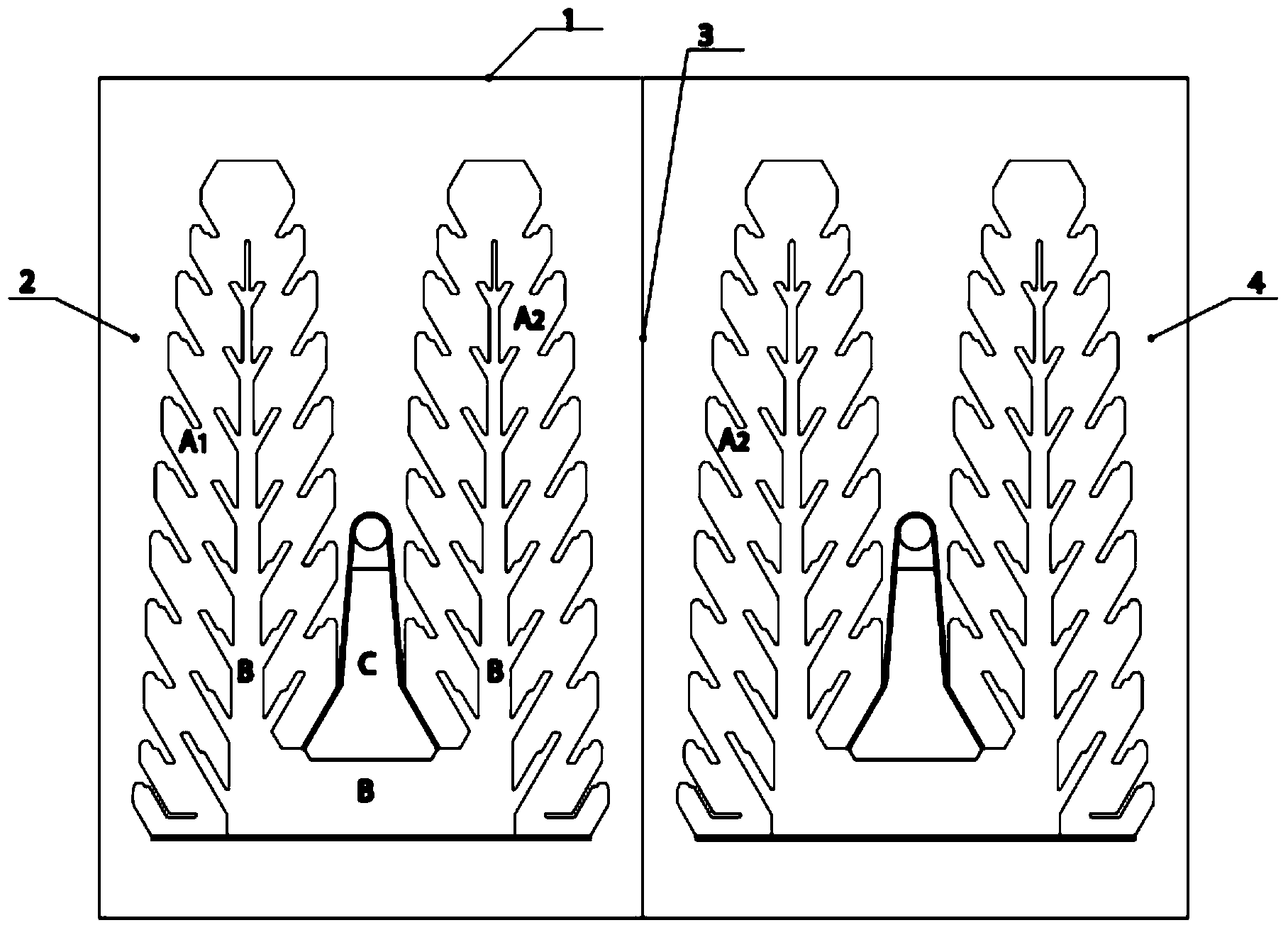
[0033] This embodiment is a cooling water single tube structure, such as figure 1 As shown, the tube bundle part of the condenser is formed by two identical tube bundles of the present invention arranged symmetrically. The periphery of the left module tube bundle forms the left main steam channel 2 with the left side of the condenser shell 1, the middle main steam channel 3 is formed between the two tube bundle modules, and the periphery of the right module tube bundle forms with the right side of the condenser shell Right main steam channel 4. The setting of the width of the main steam channel should be based on the fact that the flow velocity of the steam in this place is 70-90m / s. If the width of the main steam channel is too large or too small, the steam flow field will be unreasonable, resulting in a decrease in heat transfer or a decrease in steam resistance. Increase.

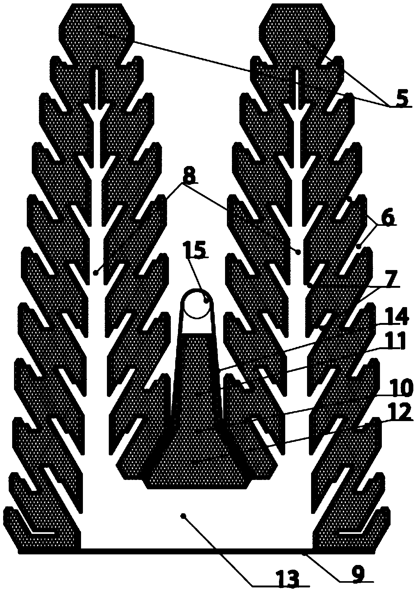
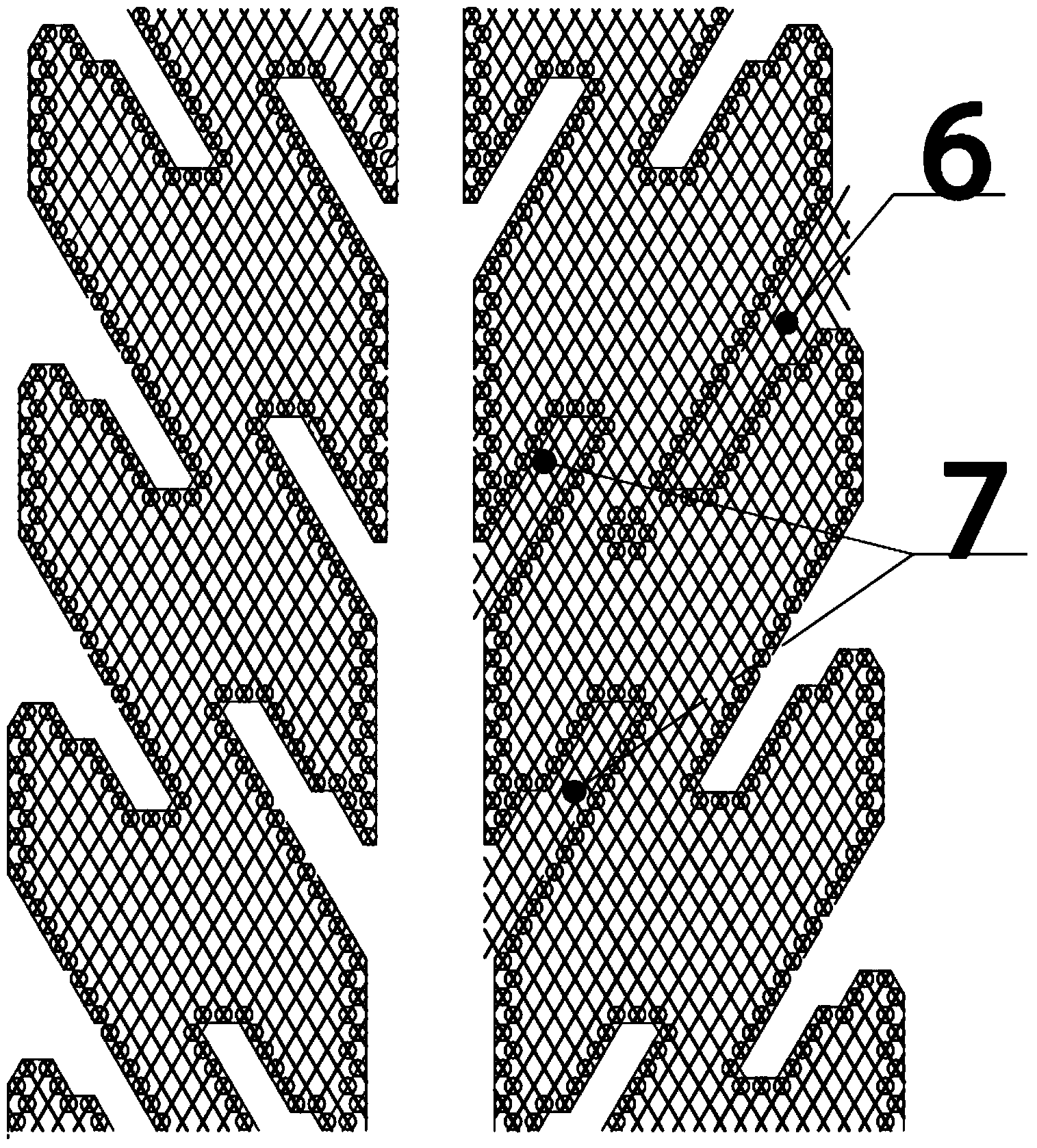
[0034] exist figure 1 In the above, taking the tube bundle on the left as an example, the tube bun...

Embodiment 2

[0043] The similarities between this embodiment and the first embodiment will not be described, and only the differences will be described.

[0044] In this embodiment, the tube bundle is a cooling water double-tube structure with upper and lower halves, such as Figure 6 As shown, the middle part of the tube bundle is provided with a plurality of zigzag split-range steam baffles 16 .

Embodiment 3

[0046] The similarities between this embodiment and the first embodiment will not be described, and only the differences will be described.

[0047] Such as Figure 7 As shown, the tube bundle part of the condenser in this embodiment is composed of four tube bundles according to the present invention, and the tube bundles are all cooling water single-pass structures.


PUM


Abstract

The invention relates to a narrow-band concurrent steam condenser tube bundle with a dual-trapezoid air cooling region. The tube bundle comprises two main condensing regions and the air cooling region between the two narrow-band concurrent main condensing regions, wherein all the main condensing regions and the air cooling region are formed by arranging cooling water tubes in a staggering manner; the outer edges of the main condensing regions are provided with a plurality of reducing steam guide passages which tilt upwards, and the inner edges of the main condensing regions are provided with a plurality of uncondensed gas collection passages which tilt downwards; the steam guide passages and the uncondensed gas collection passages are arranged in the staggering manner to partition the main condensing regions into turned narrow-band ribbons; the air cooling region is integrally elongated and consists of an upper trapezoid and a lower trapezoid; steam uniformly and concurrently flows into the main condensing regions for condensation through the guide passages, and the remaining uncondensed gas flows into the elongated air cooling region for further cooling through the uncondensed gas collection passages. Compared with the prior art, the tube bundle has the advantages of small steam resistance, full condensation, high air concentration at an outlet and capability of exhausting uncondensed gas by using exhaust equipment under low exhaust pressure without increasing the pressure of a steam condenser.

Description

technical field [0001] The invention relates to a condenser tube bundle, in particular to a narrow-band downstream condenser tube bundle with double trapezoidal air-cooling zones. Background technique [0002] The function of the large-scale power station condenser is to condense the exhaust steam discharged from the steam turbine into water and establish and maintain a certain vacuum value at the steam exhaust port of the steam turbine. The heat transfer performance of the condenser in a large power station has a great influence on the energy consumption of the unit, and the rationality of the cooling tube bundle arrangement of the condenser has an important influence on the heat transfer performance of the condenser. [0003] At present, there are many types of condenser tube bundles in power stations, typical ones are: church window tube bundle, gable tube bundle, centripetal tube bundle, AT tube bundle, vertical balanced flow tube bundle, general cap tube bundle, radial ...

Claims


Application Information

Patent Timeline
Patent Type & Authority Applications(China)
IPC IPC(8): F28B1/06F28B9/08
Inventor 张莉何坚忍姚秀平程浩然刘江王富华宋建涛
Owner SHANGHAI UNIVERSITY OF ELECTRIC POWER
Why Eureka
Try Eureka