Improved large-size generator set condenser

A technology for generating sets and condensers, applied in steam/steam condensers, lighting and heating equipment, etc., can solve the problem of reducing the operating economy and output of generating sets, affecting the safety and reliability of generating sets, and supercooling of condensed water In order to avoid problems such as high temperature, it can achieve the effect of low transformation cost, fast installation and uniform heat load distribution

Active Publication Date: 2013-08-28
MAOMING MAOGANG ELECTRIC POWER EQUIP FACTORY
View PDF5 Cites 0 Cited by
  • Summary
  • Abstract
  • Description
  • Claims
  • Application Information

AI Technical Summary

Problems solved by technology

[0004] In the prior art, the condenser tube bundles are arranged in mountain-shaped tube bundles, cathedral window-shaped tube bundles, oval tube bundles, etc. However, on the one hand, these tube bundle layouts all have eddy current dead zones to varying degrees, and the steam flow resistance is large. , high degree of supercooling of condensed water, poor condensation effect, etc.; on the other hand, the layout of these condenser tube bundles requires major changes to the condenser tube bundle and condenser structure, especially for large generator sets For the condenser, major changes to the equipment will cause a significant increase in investment, and not only reduce the economy and output of the generator set operation, but even affect the safety and reliability of the generator set operation

Method used


Image

  • Improved large-size generator set condenser
  • Improved large-size generator set condenser
  • Improved large-size generator set condenser

Examples


Embodiment 1

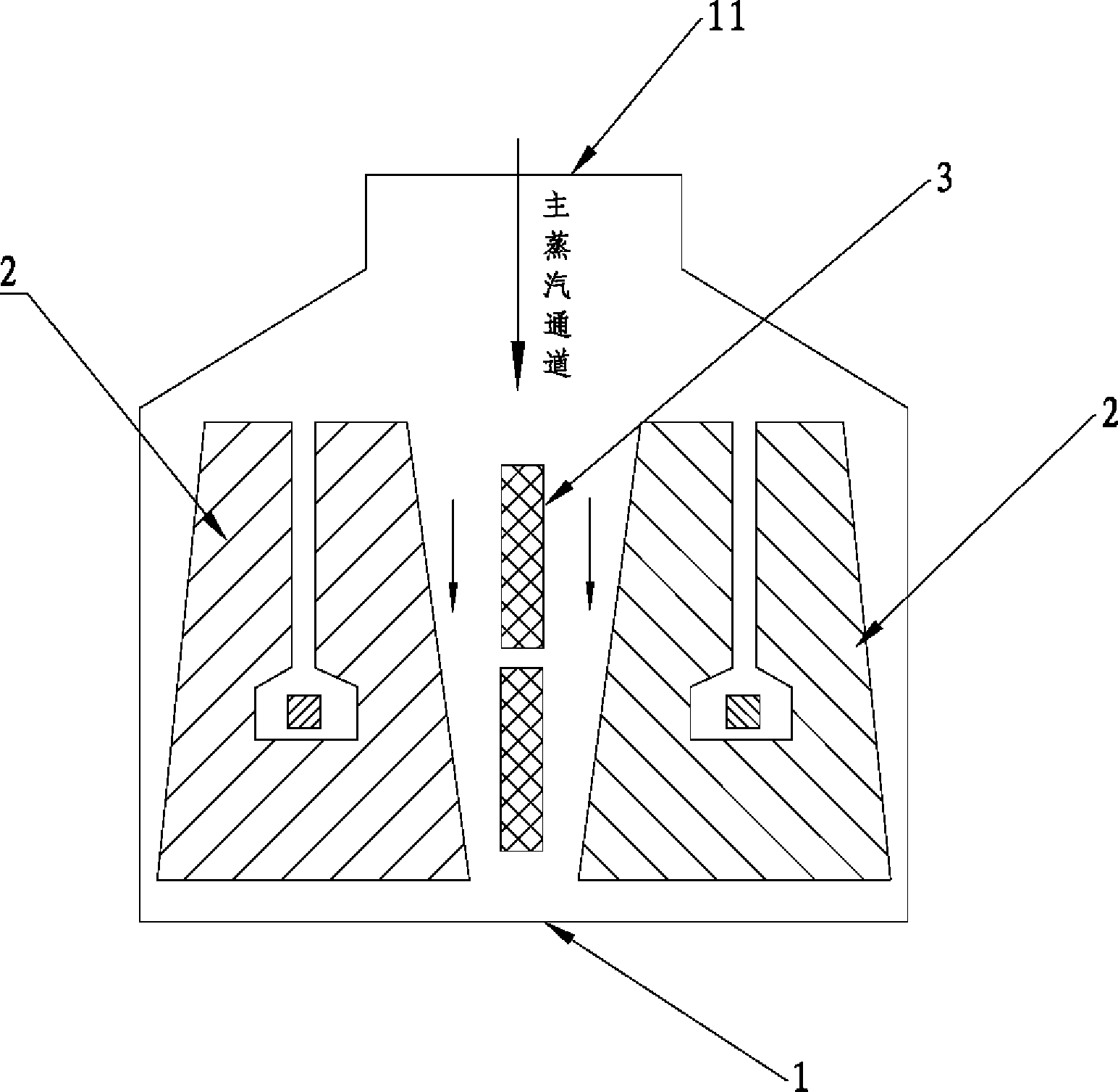
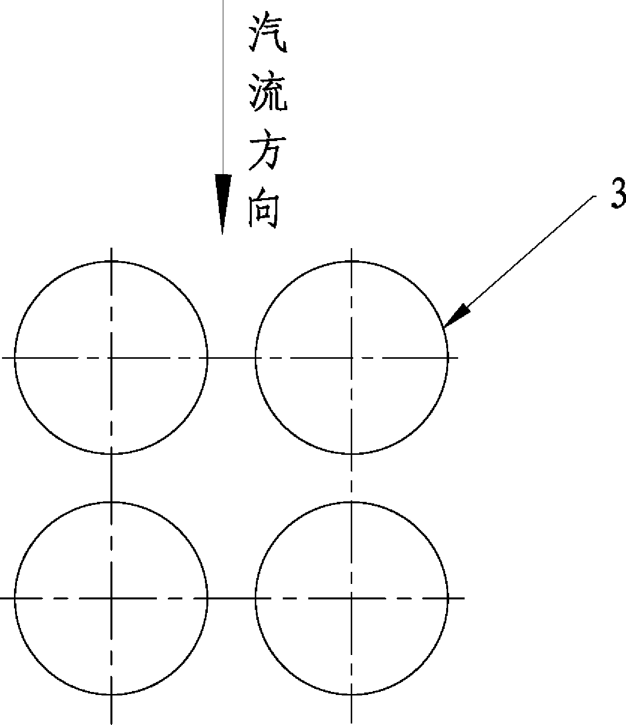
[0042] An improved large -scale generator crew, such as figure 1 As well as figure 2 and image 3 It shows that the two groups of main condensation pipe bundles 2 in the shell 1, and the end of the shell 1 are set with steam entrance 11, and the two groups of main condensate tubes 2 are set in the direction of the steam circulation in the shell 1 respectively.On both sides, the main steam channel is formed, and there are multiple sets of heat exchanges 3 in the middle of the main steam channel. Multi -group heat exchanges bundle 3 is arranged in matrix, and the number and vertical layout of each horizontal arrangement of heat exchanges 3The number of heat exchanges 3 is equal;

[0043] The gap between the adjacent heat exchanges bundle 3 in multiple groups of heat exchanges 3 is equal; and the steam passage is set up between the thermal change tube 3 and the main coagulation tube bundle 2 on the outside.

[0044] In this embodiment, under the premise of not affecting the safe opera...

Embodiment 2

[0055] Taking the 600MW large -scale generator crew as an example, the structure after the renovation of the condenser is the same as the embodiment 1. The analysis of its transformation cost and energy saving benefits is as follows:

[0056] 1. The condenser before the transformation

[0057] 1. Main technical data

[0058] 1.1 Gas with a condenser model N-36000-4

[0059] 1.2 Type -type double -back pressure, double shell, single process, surface, horizontal layout

[0060] 1.3 cooling area

[0061] Total cooling area 36000M 2

[0062] Cooling area of condensa A cooling area 18000M 2

[0063] Cooling area of condenser B 18000M 2

[0064] 1.4 Cooling medium seawater

[0065] 1.5 Design cooling water import temperature 21.9 ℃

[0066] 1.6 Design cooling water 20.85m3 / s

[0067] 1.7 Design flow rate in the cooling water pipe 2.24m / s

[0068] 1.8 Concubine water resistance ≤ 90kPa

[0069] 1.9 Design pressure (vacuum) of the condenser

[0070] Average back pressure 4.9kPa

[0071...


PUM


Abstract

The invention relates to the technical field of condensers, in particular to an improved large-size generator set condenser. The improved large-size generator set condenser comprises a shell body and two sets of main condensing tube bundles, wherein the main condensing tube bundles are arranged inside the shell body, one end of the shell body is provided with a steam inlet, the two sets of main condensing tube bundles are arranged on two sides of the inner portion of the shell body respectively in the steam flowing direction, a main steam channel is formed between the two sets of main condensing tube bundles, a plurality of sets of heat exchanging tube bundles are arranged in the middle of the main steam channel and arranged in a matrix mode, the number of transverse heat exchanging tube bundles is equal to the number of longitudinal heat exchanging tube bundles, the interval between every two adjacent heat exchanging tube bundles is the same, and a steam channel is formed between the heat exchanging tube bundles and the main condensing tube bundle outside the heat exchanging tube bundles. Compared with the prior art, the improved large-size generator set condenser reasonably increases the heat exchanging area and reasonably arranges added heat exchanging tube bundles so that aims of improving the vacuum degree of the condenser and reducing energy consumption are achieved, improving cost is low, a pay back period is greatly shortened, and the improved large-size generator set condenser is particularly suitable for energy-saving improvement of large-size generator set condensers with small cooling areas.

Description

Technical field [0001] The present invention involves the field of condenser technology, especially a large -scale large generator crew condenser. Background technique [0002] At present, there are more than 600 power plants and thermal power plants in China, most of which use the condensate steam turbine generator set, and the condenser is an important part of the turbine generator set.Establish vacuum and maintain vacuum at the steam turbines.The vacuum of the condenser has a great impact on the operational safety and thermal economy of the generator set. [0003] According to statistics, compared with similar units in industrial developed countries, the thermal generators below 600MW are generally low and high in thermal consumption.%~ 1%.For example, the vacuum of domestic introduction of 300MW generator sets is generally between 91%and 94%, which is 3 to 6 percentage points lower than the design value, resulting in an increase of 8.16g / kWh of the power supply consumption of...

Claims


Application Information

Patent Timeline
Patent Type & Authority Applications(China)
IPC IPC(8): F28B1/02
Inventor 叶加贵黄素逸李权关欣吕圣杰唐悦中李灼南尤天运
Owner MAOMING MAOGANG ELECTRIC POWER EQUIP FACTORY
Why Eureka
Try Eureka