Device for quickly collecting oil and gas leaked from oil-gas storage tank

A technology of oil and gas storage tanks and collection devices, applied in packaging, transportation, packaging, containers, etc., can solve the problems of complex maintenance process, increased operating costs, and difficult operation, and achieve improved safety factor, low maintenance cost, and simple operation Effect

Inactive Publication Date: 2017-06-30
CHINA UNIV OF PETROLEUM (EAST CHINA)
View PDF6 Cites 2 Cited by
  • Summary
  • Abstract
  • Description
  • Claims
  • Application Information

AI Technical Summary

Problems solved by technology

[0003] Due to third-party damage and rotten candle damage to the tank body in the tank area, oil tank leakage will occur. After the oil leaks, it will flow to the ground, and will flow along the ground to low-lying places or artificial boundaries, forming a liquid pool. The fire source will form a pool fire, which will endanger the surrounding oil tanks
The common method of repairing storage tanks is only welding, but it has the disadvantages of complicated maintenance process, difficult operation, high risk factor, attention to the selection of welding materials, and the number of welding repairs on the same part cannot exceed twice, especially for gas storage tank welding and oil storage. Repair welding with tank oil is more dangerous
In the maintenance of storage tanks, once improper operation or violation of regulations, major accidents are likely to occur, causing casualties and property losses
In addition, when a storage tank is damaged and leaks, it is generally not possible to repair it immediately. Instead, the oil and gas in the tank are introduced into the spare tank, and then centralized maintenance, which greatly increases the operating cost
[0004] The oil and gas tank area has the characteristics of high safety risk, heavy accident consequences, wide range of influence, difficult rescue, and high social concern. Therefore, safety supervision must be strengthened to ensure the safe operation of oil tanks

Method used


Image

  • Device for quickly collecting oil and gas leaked from oil-gas storage tank
  • Device for quickly collecting oil and gas leaked from oil-gas storage tank

Examples


Embodiment Construction

[0012] Below in conjunction with accompanying drawing and example the present invention will be further described:

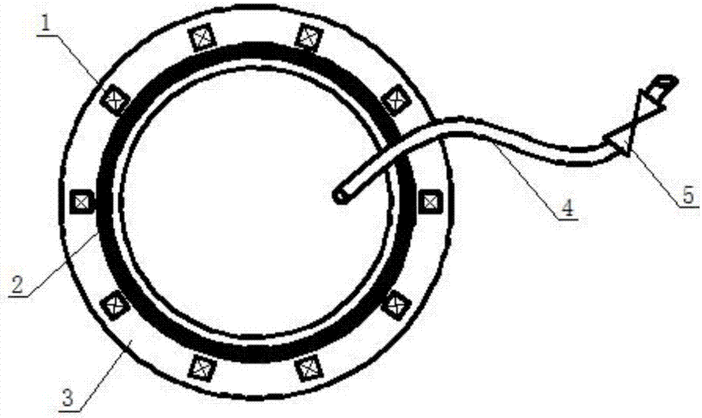
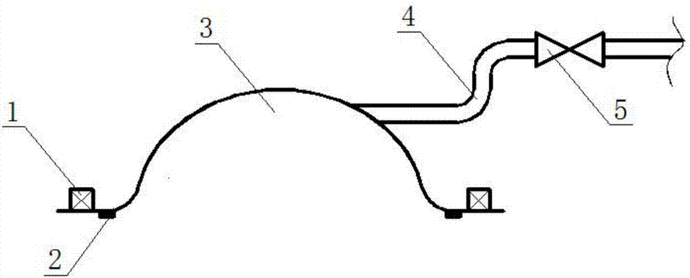
[0013] Such as Figure 1-2 As shown, the device for quickly collecting oil and gas leaked from an oil and gas storage tank provided by the present invention includes a magnet (1), a sealing ring (2), a rubber bladder (3), a conduit (4), a valve (5), a magnet (1) and a storage tank The tanks are attracted to each other, the rubber bladder (3) has a sealing ring (2), the rubber bladder (3) is fixed on the storage tank by the magnetic force between the magnet (1) and the storage tank, and the conduit (4) is connected with the rubber bladder ( 3), a valve (5) is installed on the conduit (4).

[0014] The specific steps for rapid collection of leaked oil and gas by the oil and gas storage tank leakage oil and gas rapid collection device provided in this embodiment are:

[0015] When the oil and gas storage tank leaks, first cover the leak with a rubber bag with a s...


PUM


Abstract

The invention provides a device for quickly collecting oil and gas leaked from an oil-gas storage tank, and relates to a leaked oil and gas collecting device. According to the technical scheme, the device comprises a magnet, a seal ring, a rubber skin, a guide tube and a valve, wherein the magnet and the storage tank attract each other; the rubber skin is equipped with the seal ring, and fixed on the storage tank by utilizing the magnetic force between the magnet and the storage tank; the guide tube is connected with the rubber skin; and the valve is mounted on the guide tube. The device has the beneficial effects of being simple to operate and low in maintenance cost; open flames can be avoided and the safety coefficient can be improved; the safe operation of an oil storage tank field is not influenced; the operation cost is reduced; and the oil and gas of the oil-gas storage tank can be effectively and quickly collected.

Description

technical field [0001] The invention relates to a device for quickly collecting oil and gas leaked from an oil and gas storage tank, in particular to a device for collecting leaked oil and gas. Background technique [0002] With the increase of the production scale of the petrochemical industry, dangerous substances such as oil and natural gas are used in large quantities and frequently, thereby increasing the possibility of major accidental leakage. The oil or gas stored in the tank area is toxic, volatile, flammable and explosive, and is very dangerous. Once a leak or fire occurs in the tank area, its scope and degree of influence are relatively large, and it belongs to the second-level major hazard source. If it is not paid attention to, it will cause a huge threat to people's life and property safety, cause huge economic losses to the country, and severely damage the environment. It is irreparable. Therefore, in order to minimize the probability of accident risk, it is...

Claims


Application Information

Patent Timeline
Patent Type & Authority Applications(China)
IPC IPC(8): B65D90/30
CPCB65D90/30
Inventor 蒋文明侯丹阳刘杨
Owner CHINA UNIV OF PETROLEUM (EAST CHINA)
Why Eureka
Try Eureka