Noncontact electromagnetic passive cutting magnetic line power taking device and method

A non-contact technology for cutting magnetic induction lines, which is applied in battery circuit devices, circuit devices, electric vehicles, etc. Effect

Active Publication Date: 2018-10-26
SHANGHAI UNIV OF ENG SCI +1
View PDF5 Cites 2 Cited by
  • Summary
  • Abstract
  • Description
  • Claims
  • Application Information

AI Technical Summary

Problems solved by technology

[0004] The purpose of the present invention is to provide a non-contact electromagnetic type passive cutting magnetic induction line power harvesting device and method in order to overcome the defects of the above-mentioned prior art, so as to solve the problem of insufficient power when the UAV is cruising on the UHV transmission line

Method used


Image

  • Noncontact electromagnetic passive cutting magnetic line power taking device and method

Examples


Embodiment

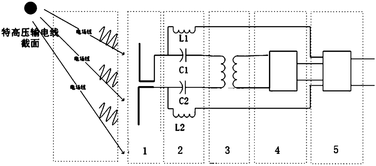
[0024] figure 1 It is a schematic diagram of the power extraction principle of the present invention, which mainly includes a high-voltage transmission line, a wireless receiving antenna 1, a separation circuit 2, a transformer 3, a rectifier module 4, and a voltage stabilization module 5.

[0025] A. In the UHV AC transmission circuit:

[0026] On the one hand, the wireless receiving antenna is subjected to the electromagnetic wave generated by the UHV alternating transmission line (generated by the line, and the line halo phenomenon) to generate an alternating electromotive force. When the wireless receiving antenna is cut by the magnetic force line of the electromagnetic wave in the air, it will A certain alternating voltage is excited at the terminal.

[0027] On the other hand, the wireless receiving antenna is affected by the alternating electric field generated by the UHV alternating transmission line, and an alternating induced electromotive force is generated at both...


PUM


Abstract

The invention relates to a noncontact electromagnetic passive cutting magnetic line power taking device which is arranged on an unmanned aerial vehicle. The device comprises an antenna (1), a separation circuit (2), a transformer (3), a rectifying module (4) and a voltage stabilizing module (5) which are connected in turn. When the unmanned aerial vehicle flies near the ultrahigh voltage power transmission line, the antenna (1) generates induced voltage and electromotive force because of the effect of the magnetic field and the electric field in the power transmission line. The separation circuit (2) transmits the alternating current generated in the antenna (1) to the voltage stabilizing module (5) through the transformer (3) and the rectifying module (4) and directly transmits the directcurrent generated in the antenna (1) to the voltage stabilizing module (5). The voltage stabilizing module (5) outputs rated power for charging of the unmanned aerial vehicle. Compared with the devices in the prior art, the working power required for charging of the storage battery of the unmanned aerial vehicle can be stably obtained so that the effect is obvious, and the device is favorable forpopularization and application in the field of online monitoring of the power grid equipment and especially can enhance the high voltage line power transmission unmanned aerial vehicle inspection endurance capacity.

Description

technical field [0001] The invention relates to a wireless charging method, in particular to a non-contact electromagnetic type passive cutting magnetic induction line power-taking device and method. Background technique [0002] With the rapid development of the national economy, the power transmission capacity and transmission distance have increased rapidly, and large-capacity, long-distance transmission lines have been put into operation. The transmission voltage has also increased, and the requirements for line safety have become higher and higher. UHV transmission lines generally refer to transmission lines that carry the above voltages. [0003] In order to solve the threat to power grid security caused by frequent disasters in recent years, many domestic power companies have begun to use special unmanned helicopters to inspect high-voltage power lines. UAVs use batteries as built-in power sources. However, due to the limited power of batteries, UAVs cannot fly long ...

Claims


Application Information

Patent Timeline
Patent Type & Authority Applications(China)
IPC IPC(8): H02J50/20H02J7/00
CPCH02J7/025H02J50/20
Inventor 贺超吴飞黄敏汪茹舒野张菁宋梁包中福雷泽宇赵强刘意杨蔚周辉
Owner SHANGHAI UNIV OF ENG SCI
Why Eureka
Try Eureka