Stereoscopic display unit and production method thereof

A stereoscopic display device and display control technology, applied in stereoscopic systems, optics, instruments, etc., can solve the problems of resolution sacrifice, uneven brightness distribution, moiré, etc.

Active Publication Date: 2015-01-07
SHENZHEN CHINA STAR OPTOELECTRONICS TECH CO LTD
View PDF4 Cites 6 Cited by
  • Summary
  • Abstract
  • Description
  • Claims
  • Application Information

AI Technical Summary

Problems solved by technology

Stereoscopic display devices in the prior art generally use a lenticular lens array, the purpose of which is to solve the problem of uneven brightness distribution so that observers can observe images with uniform brightness distribution
[0003] figure 1 It is a structural schematic diagram of a stereoscopic display device in the prior art, such as figure 1 As shown, taking 8 viewpoints as an example, the grating lens includes 8 lens units periodically arranged along the row direction, so the resolution in the row direction is seriously sacrificed, only 1 / 8 of the original, because the grating lens and the pixel arrangement of the display panel have high The similarity of the frequency, that is, the grating lens group and the black matrix on the display panel have an equal periodic structure, which makes it easy to form a beat and produce moiré

Method used


Image

  • Stereoscopic display unit and production method thereof
  • Stereoscopic display unit and production method thereof
  • Stereoscopic display unit and production method thereof

Examples


Embodiment Construction

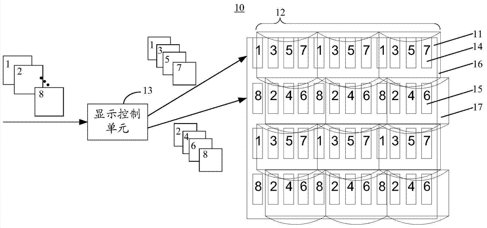
[0031] see figure 2 , figure 2 is a schematic structural view of the stereoscopic display device according to the first embodiment of the present invention. Such as figure 2 As shown, the stereoscopic display device 10 includes a display panel 11 , a grating lens 12 and a display control unit 13 . The display panel 11 includes a first row of sub-pixels 14 and a second row of sub-pixels 15 arranged adjacently along the column direction. The first row of sub-pixels 14 and the second row of sub-pixels 15 respectively include a plurality of sub-pixels arranged periodically along the row direction. The display control unit 13 acquires a plurality of viewpoint images, and divides the plurality of viewpoint images into a first group of viewpoint images and a second group of viewpoint images. The display control unit 13 further controls the first row of sub-pixels 14 to periodically display the content of each viewpoint image in the first group of viewpoint images, and controls...


PUM


Abstract

The invention discloses a stereoscopic display unit and a production method thereof. The stereoscopic display unit comprises a display panel, a display control unit and a grating lens, the display panel comprises a first row of sub-pixels and a second row of sub-pixels arranged adjacently along the column direction, the display control unit acquires multiple viewpoint images which are divided into a first group of viewpoint images and a second group of viewpoint images, further the first row of sub-pixels is controlled to periodically display content of each viewpoint image in the first group of viewpoint images, the second row of sub-pixels is controlled to periodically display content of each viewpoint image in the second group of viewpoint images, the grating lens comprises a first row of lens units and a second row of lens units arranged adjacently along the column direction, the first row of lens units and the second row of lens units respectively cover the first row of sub-pixels and the second row of sub-pixels, the lens units in the first row of lens units and the lens units in the second row of lens units are staggered mutually along the row direction, and the stagger amount is smaller than one sub-pixel period. By the means, moire can be eliminated, and the problem of crosstalk between the adjacent pixel units can be solved.

Description

technical field [0001] The invention relates to the field of portable electronic equipment, in particular to a stereoscopic display device and a manufacturing method thereof. Background technique [0002] Currently, display technology has developed from 2D display to 3D display. The existing naked-eye stereoscopic display device is mainly developed based on binocular parallax. Its main working principle is to guide two images with a certain parallax to the left eye and right eye of the observer respectively through a lens array or a parallax barrier, so that the observer can observe The user feels the three-dimensional effect. The current glasses-free 3D display technology can be realized by using a parallax barrier, a lenticular lens, or a directional backlight. The stereoscopic display device in the prior art generally adopts a lenticular lens array, in order to solve the problem of uneven brightness distribution so that observers can observe images with uniform brightne...

Claims


Application Information

Patent Timeline
Patent Type & Authority Applications(China)
IPC IPC(8): G02F1/1335G02B27/22H04N13/04
CPCH04N13/305G02F1/133526G02B30/27H04N13/351H04N13/315G02F1/1335
Inventor 廖巧生
Owner SHENZHEN CHINA STAR OPTOELECTRONICS TECH CO LTD
Why Eureka
Try Eureka