Longitudinal differential protection current phase compensation method for wiring transformer YNd3

A technology of current phase compensation and differential protection, applied in emergency protection circuit devices, electrical components, etc., can solve the problems of inability to adapt to wiring groups and wiring combinations, and achieve the effect of small changes in the secondary circuit and easy implementation.

Inactive Publication Date: 2015-01-07
STATE GRID CORP OF CHINA +2
View PDF4 Cites 4 Cited by
  • Summary
  • Abstract
  • Description
  • Claims
  • Application Information

AI Technical Summary

Problems solved by technology

However, at present, the differential protection current software phase compensation method of various transformer protection manufacturers usually only develops several commonly used transformer wiring groups, such as YNd1 wiring group and its wiring combination, etc., and cannot adapt to other wiring groups and wiring combinations.

Method used


Image

  • Longitudinal differential protection current phase compensation method for wiring transformer YNd3
  • Longitudinal differential protection current phase compensation method for wiring transformer YNd3
  • Longitudinal differential protection current phase compensation method for wiring transformer YNd3

Examples


Embodiment Construction

[0017] specific implementation plan

[0018] 1. Phase relationship between YNd3 wiring transformer and YNd1 series wiring transformer

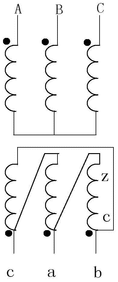
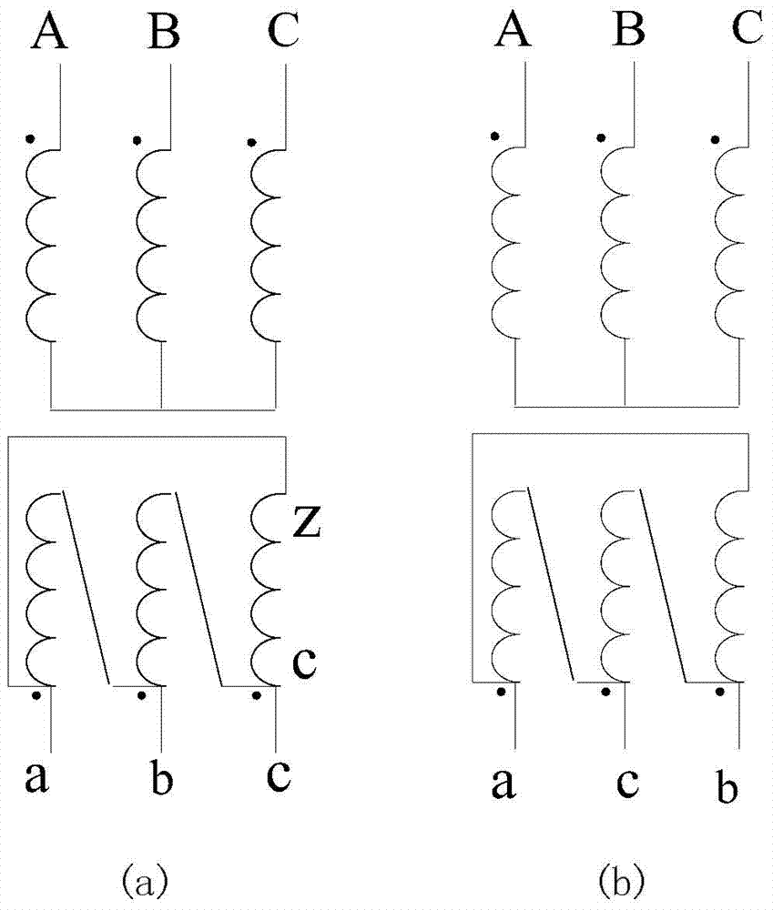
[0019] YNd3 wiring transformer wiring diagram see figure 1 . Because the three-phase voltages on the high-voltage side and low-voltage side of the YNd3 transformer are symmetrical, only one line voltage is used for comparison, so there is advanced 90 degrees. YNd1 wiring transformer wiring diagram see figure 2 a), same as YNd1 transformer advanced Spend. We put the YNd3 transformer with YNd1 transformer Consider the same phase, compare the low voltage side of YNd1 transformer and YNd3 transformer The relationship between. and figure 1 Medium YNd3 transformer low voltage side is the voltage of the low-voltage c winding on the C-phase iron core column exist figure 2 In a), we can also find the voltage of the low voltage c winding on the C phase iron core column (It is regarded as equivalent to the low-voltage side of ...


PUM


Abstract

The invention belongs to the technology of relay protection control of electric power transmission and distribution networks and relates to a longitudinal differential protection current phase compensation method for a wiring transformer YNd3. The method comprises the steps that an a-phase current of a secondary winding TA on the side d of the wiring transformer YNd3 is connected into an a-phase current circuit on the side d of a wiring microcomputer transformer differential protective device YNd1; a c-phase current of the secondary winding TA on the side d of the wiring transformer YNd3 is connected into a b-phase current circuit on the side d of the wiring microcomputer transformer differential protective device YNd1; a b-phase current of the secondary winding TA on the side d of the wiring transformer YNd3 is connected into a c-phase current circuit on the side d of the wiring microcomputer transformer differential protective device YNd1; phase compensation is conducted on a differential protective device of the wiring transformer YNd3 according to software phase compensation of the wiring microcomputer transformer differential protective device YNd1. By means of the method, current phase compensation of the differential protective device of the wiring transformer YNd3 can be completed; moreover, the method is simple in principle and convenient to implement.

Description

technical field [0001] The invention belongs to the relay protection control technology of electric power transmission and distribution network, and relates to a method for current phase compensation of YNd3 connection transformer longitudinal differential protection. Background technique [0002] Since the phases of the currents on each side of the transformer may be inconsistent, the transformer longitudinal differential protection (hereinafter referred to as the transformer differential protection) needs to perform current phase compensation. There are two methods of current phase compensation for transformer differential protection: 1. Traditional hardware phase shifting: For example, the secondary winding of Y-side current transformer (hereinafter referred to as TA) of YNd11 transformer adopts delta d-11 connection, and the secondary winding of d-side TA Use star Y-12 wiring; 2. Software phase shift: use software program and calculation formula to carry out current phas...

Claims


Application Information

Patent Timeline
IPC IPC(8): H02H7/045
Inventor 汤大海杜云龙马海薇
Owner STATE GRID CORP OF CHINA
Why Eureka
Try Eureka