
Emergency hood porous oxygen inhalation and exhaust device for hyperbaric oxygen chamber

A technology of an oxygen exhaust device and a hyperbaric oxygen chamber, which is used in respirator, life-saving equipment, respiratory protection container, etc., can solve problems such as co-infection, dry respiratory mucosa, and ineffective oxygen exhaust methods, and achieve the effect of solving oxygen exhaust problems.

Inactive Publication Date: 2015-01-14
王有存
View PDF6 Cites 3 Cited by
  • Summary
  • Abstract
  • Description
  • Claims
  • Application Information

AI Technical Summary

Problems solved by technology

[0006] (4) The position of the emergency oxygen inhalation valve is fixed and single, and it cannot be connected with the ventilator and the breathing airbag.
[0007] (5) Oxygen is not humidified and filtered, which can easily cause dryness of the respiratory mucosa and even rupture of capillaries, cough, thick sputum and co-infection at the same time. It is not suitable for the rescue of lung infection, tracheotomy and critically ill patients
However, the reason for the increase of oxygen concentration in the cabins of many units is due to the emergency oxygen inhalation hood and ineffective oxygen exhaust methods.
According to the national standard of "Medical Air Pressurized Chamber" (GB / T12130-2005), the oxygen concentration in the cabin is required to be no more than 23%, but it is difficult to control it below 23% when the cabin volume is small and there are many hoods in the cabin

Method used


Image

  • Emergency hood porous oxygen inhalation and exhaust device for hyperbaric oxygen chamber

Examples


Embodiment Construction

[0016] In order to facilitate those skilled in the art to better understand the present invention, the present invention will be described in further detail below in conjunction with the accompanying drawings and specific embodiments. The following is only exemplary and does not limit the protection scope of the present invention.

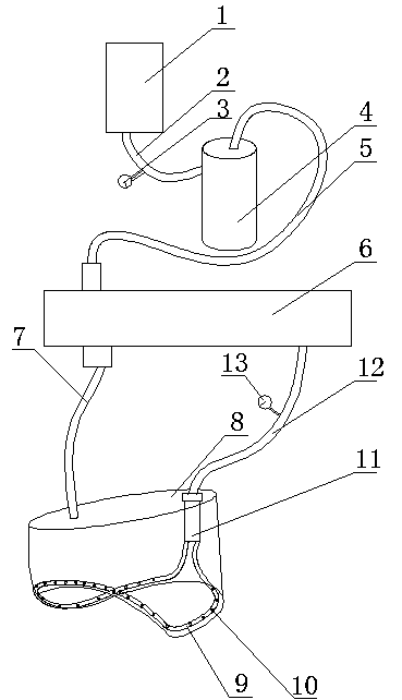
[0017] Reference attached figure 1 , a hyperbaric oxygen chamber first aid hood porous oxygen suction and exhaust device, including an oxygen source 1, a buffer humidification filter 4, an airflow guide valve box 6, a hood 8, an oxygen exhaust flowmeter 13 and an oxygen supply flowmeter 3, the oxygen The source 1 is connected to one end of the first oxygen supply pipe 2, the other end of the first oxygen supply pipe 2 is connected to the oxygen inlet end of the buffer humidification filter 4, and the oxygen outlet end of the buffer humidification filter 4 is connected to the air flow through the second oxygen supply pipe 5 Guide valve box 6 supply ...


PUM


Abstract

The invention provides an emergency hood porous oxygen inhalation and exhaust device in a hyperbaric oxygen chamber. By adopting the emergency hood porous oxygen inhalation and exhaust device, the oxygen exhaust problem is well solved, and the aims of safety, reliability and convenience in use are achieved. The device comprises an oxygen source, a buffer humidification sensor, an airflow guide valve box, a hood, an oxygen exhaust flowmeter and an oxygen supply flowmeter, wherein the oxygen source is connected with one end of a first oxygen supply pipe; the other end of the first oxygen supply pipe is connected with the oxygen inlet end of the buffer humidification sensor; the oxygen outlet end of the buffer humidification sensor is communicated with the supply end of the airflow guide valve box through a second oxygen supply pipe; an oxygen outlet pipe and an oxygen inlet pipe are arranged on the hood; an air outlet pipe is arranged at the periphery of the hood; multiple air holes are formed in the air outlet pipe; the upper end of the oxygen inlet pipe is arranged at the inhalation end of the airflow guide valve box; the lower end of the oxygen inlet pipe is arranged at the air inlet end of the hood; the upper end of the oxygen outlet pipe is arranged at the exhalation end of the airflow guide valve box; the lower end of the oxygen outlet pipe is arranged at the air outlet end of the hood; two ends of the air outlet pipe are connected with an oxygen exhaust pipe through a tee joint; and the oxygen exhaust flowmeter is arranged on the oxygen exhaust pipe.

Description

technical field [0001] The invention relates to a medical auxiliary device, in particular to a porous oxygen inhalation and exhaust device for a hyperbaric oxygen chamber emergency head mask. Background technique [0002] In hyperbaric oxygen therapy, in order to solve the problems of comatose patients, infants, tracheotomy, weak breathing, and small breathing movement, in the past, hyperbaric oxygen chambers were equipped with ① "open" emergency oxygen breathing hood or ② "active Petal type" first aid oxygen breathing and exhausting hood. The above two kinds of emergency oxygen inhalation hoods all have one or another problem in clinical use, and cannot achieve the purpose of effective oxygen exhaustion. Their shortcomings and deficiencies are as follows: [0003] (1) A separate oxygen supply line is used to control the flow through the centralized console outside the cabin. The medical staff in the cabin cannot use it directly. When oxygen supply, oxygen stop and adju...

Claims


Application Information

Patent Timeline
Patent Type & Authority Applications(China)
IPC IPC(8): A61G10/02A61M16/00A61M16/16
Inventor 王有存陈庆莹尉蔚王君峰边永辉邵帅公涛唐茜彭勇静
Owner 王有存
Learn More